background image

R

epair

P 3 / 15 

Fig. 2

Fig. 3

Fig. 4

Fig. 5

Fig. 6

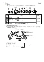
< 4 > Disassembling spindle (as a bit holder) and clutch case

( 1 ) After removing bit holder section, remove ring 38 by unscrewing pan head screw M4x4, and  clutch case cover 
        by unscrewing pan head screw M4x8.  And then, remove compression spring 2 and switch lever.  See Fig. 2.

( 2 ) Remove clutch case by unscrewing 4 pcs. of pan head screw M4x22.  See Fig. 3.

( 3 ) Remove retaining ring R-21 from clutch case. And then, knock the edge of clutch case with plastic hammer.
        So, spindle (as a bit holder) can be removed from  clutch case.  See Fig. 4.
( 4 ) Remove ring spring 11 from spindle.  And then remove ball bearing 6801LLB on the ring spring 11 side.
        See Fig. 5.

( 5 ) After removing ring 12, remove the another ball bearing 6801lLB.  See Fig. 6.

Pan head screw M4x8
(black)

Clutch case cover

Clutch case

Compression 
spring 2

Clutch case

Clutch section

Switch lever

Pan head
 screw M4x22

Compression 
spring 5

No.1R311
Retaining Ring Pliers 
with Long Bent Nails

Retaining ring R-21

Spindle

Ring 12

Ball bearing
6801LLB

Ring spring 11


1R269 

Bearing Extractor

Ball bearing 6801lLB

Ball bearing 6801lLB

Ring 12

Spindle

1R004
Retaining ring S plier

Pan head 
screw M4x4 (silver)

Ring 38

< Note > Compression spring 5 can easily fall off clutch section. Be careful, not to lose compression spring 5
               in this step.

Summary of Contents for BFT040F

Page 1: ...developed for fastening works in assembling line Their common feature and benefits are as follows New charging system Higher accuracy in fastening torque Superior handling BHT123F 12V is applicable to...

Page 2: ...ole portion Whole portion Teeth portion which engages 49 spur gear 48 49 Spur gear 19 54 1 0 04 1 0 04 2 Disassembling bit holder section 3 Assembling bit holder section 1 Remove ring spring Then flat...

Page 3: ...See Fig 4 4 Remove ring spring 11 from spindle And then remove ball bearing 6801LLB on the ring spring 11 side See Fig 5 5 After removing ring 12 remove the another ball bearing 6801lLB See Fig 6 Pan...

Page 4: ...g spring 11 See Fig 10 5 Mount the spindle section to clutch case as illustrated in Fig 11 6 Secure the spindle section in the clutch case with retaining ring R 21 See Fig 12 7 Mount clutch section to...

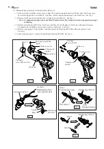
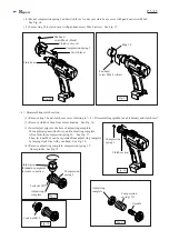
Page 5: ...mbling spindle as a bit holder and clutch case 2 Remove clutch section from motor housing See Fig 16 Clutch section Compression spring 5 4 Remove adjust ring complete compression spring 19 from spindl...

Page 6: ...head screw M5x10 Torx counter sunk head screw M5x10 Hex wrench Torx wrench T25 6mm Steel balls 3 0 13 pcs Flat washer 7 Cam A Note Pay attention not to lose steel balls when disassembling Use the hex...

Page 7: ...teel balls 5 Mount steel balls 4 to cam B Mount cam A Cam B Steel balls 4 3 pcs Steel balls 3 0 13 pcs Mount steel balls 3 0 to cam A Mount flat washer 7 to cam A Pay attention not to spot the screw h...

Page 8: ...m housing R 4 Turn motor bracket anti clockwise So gear section can be separated from motor section See Fig 35 5 Remove endbell from motor armature And then pull armature from yoke unit See Fig 36 Bru...

Page 9: ...6805LLB and carrier complete B to gear case See Fig 40 3 Mount internal gear 47 to the gear case See Fig 41 4 Engaging internal gear 47 mount 3 pcs of spur gear 18 to the shaft portion of carrier comp...

Page 10: ...using R and put ON OFF switch with F R change lever buzzer circuit and terminal into housing R Contain LED circuit into housing R See Fig 49 12 Mount plate and lens And secure housing L with 8 pcs of...

Page 11: ...g its concave portion with the boss of ON OFF switch See Fig 52 3 Mount the switch to housing R See Fig 53 Screw Micro switch ON OFF switch Turning anti clockwise pull off the micro switch F R change...

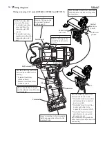
Page 12: ...Color index of lead wires Black White Red Orange Blue Yellow Purple Gray M DC Motor End bell Terminal Controller Indicator lamp is built in the controller COM NO Micro Switch ON OFF Switch M2 S1 S2 M...

Page 13: ...r circuit has to be so mounted that the sponge side is faced to the housing L side The connector has to be put on the terminal side of this line as illustrated Pass the following lead wires between ri...

Page 14: ...nted that the sponge side is faced to the housing L side The connector has to be put on the terminal side of this line as illustrated Pass the following lead wires between rib and the wall of housing...

Page 15: ...ders at clutch case Clutch case Lead holder Contain the slack portion of lead wires and connectors into this pace Controller lead wire white Controller lead wire white Controller lead wire purple Cont...

Reviews: