R
epair
P 4 / 15
Fig. 7
Fig. 8
Fig. 9
Fig. 10
Fig. 11
Fig. 12
Fig. 13
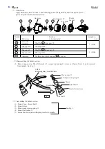
< 5 > Assembling spindle (as a bit holder) and clutch case
Ring spring 11
1R004
Retaining ring S plier
( 1 ) Set ball bearing 6801LLB on 1R035 "Bearing setting plate". Mount spindle to ball bearing 6801LLB by pressing
with arbor press. See Fig. 7
( 2 ) Mount ring 12 to spindle. See Fig. 8.
( 3 ) Set another ball bearing 6801LLB on 1R035 "Bearing setting plate". Mount spindle to the ball bearing 6801LLB
by pressing with arbor press. See Fig. 9.
( 4 ) Secure 2 pcs. of ball bearing 6801LLB and ring 12 with ring spring 11. See Fig. 10.
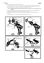
( 5 ) Mount the spindle section to clutch case as illustrated in Fig. 11.
( 6 ) Secure the spindle section in the clutch case with retaining ring R-21. See Fig. 12.
( 7 ) Mount clutch section to motor housing. Mount
compression spring 5 to the clutch section. Fasten
the clutch case to the motor housing with 4 pcs.of
pan head screw M4x22 See Fig. 13.
1R035
Bearing setting plate
1R036
Bearing setting plate
Ball bearing
6801LLB
Ball bearing
6801LLB
Spindle
Ring 12
< Note > Do not use the used ring spring 11. It has to be always replaced with the fresh one.
1R237
Round bar for arbor
Clutch case
No.1R311
Retaining Ring Pliers
with Long Bent Nails
Retaining ring R-21
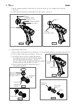
Clutch case
Clutch section
Pan head
screw M4x22
Compression
spring 5


