R
epair
P 8 / 15
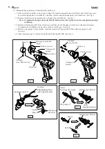
< 8 > Disassembling motor section and gear section
Fig. 33
Fig. 34
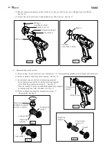
Fig. 35
Fig. 36
( 1 ) Remove ring 38, and clutch cover from housing referring to "< 4 > Disassembling spindle (as a bit holder)
and clutch case".
( 2 ) After removing brush holder caps, carbon brushes and clutch section, separate housing L from housing R
by unscrewing 8 pcs. of pan head screw M3x20. See Fig. 33.
( 3 ) Remove gear section with motor section from housing R .
( 4 ) Turn motor bracket anti-clockwise. So gear section can be separated from motor section. See Fig. 35.
( 5 ) Remove endbell from motor armature. And then, pull armature from yoke unit. See Fig. 36.
Brush holder
cap
Brush holder
cap
Carbon brush
Carbon brush
Clutch
section
Compression spring 5
Pan head
screws M3x20
Housing L
Housing R
Plate
Lens
Gear section
Motor section
See Fig. 34.
Motor bracket
Gear section
End bell
Armature
Armature
Yoke unit
Yoke unit
<Note>
Be careful, not to be pinched your finger
between yoke unit and armature.
Because, armature is pulled toward yoke
unit by the strong magnetic force.


