background image

P 7 / 14

R

epair

[3] DISASSEMBLY/ASSEMBLY
[3] -4. Tool Holder Complete and Spur Gear 51 (cont.)
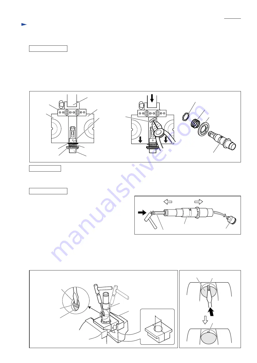
DISASSEMBLING

5) Attach two 1R022 to 1R306.
    Install them on arbor press as illustrated to left in Fig. 16.
6) Applying two 1R022 to Washer 31, press them down using arbor press in order to remove the force of
    Compression spring 32 from Ring spring 29 (center of Fig. 16).
7) While pressing Washer 31, remove Ring spring 29 from Tool holder complete. (center of Fig. 16)
8) Remove Washer 31, Compression spring 32 and Spur gear 51 from Tool holder complete. (right in Fig. 16)

ASSEMBLING

Do the reverse of the disassembling steps.

Fig. 16

[3] -5. Impact Bolt Section

DISASSEMBLING

1) Take Tool holder complete out of the machine as
    illustrated in Fig. 14 and Fig. 15.
2) Remove Striker from Tool holder complete using 1R281
    for 1R281 as illustrated in Fig. 17.
3) Clamp Tool holder complete using Vise and 1R038 as
    illustrated in Fig. 18.
4) Insert a slotted screwdriver between Ring spring 28 and
     O ring case through the side hole of Tool holder.
    Important: If you see the end of Ring spring 28 in the hole, push the spring using a slotted screwdriver until the end
                        is hidden (Fig. 19).
    Strike the slotted screwdriver with plastic hammer to remove Ring spring 28 from the groove on the inside surface of
    Tool holder complete.  Applying slotted screwdriver through the other side hole, remove Ring spring 28 from the groove
    in the same way (Fig. 18).

Fig. 17

Tool holder complete

Compression spring 32

Compression spring 32

Spur gear 51

Washer 31

Ring spring 29

1R022

1R022

Arbor press

1R306

Spur gear 51

Washer 31

Tool holder complete

Cap 35 side

Inner housing side

Striker

Tool holder complete

1R281

Ring spring 28

O ring case

Fig. 19

Fig. 18

32mm

1R038

Vise

Ring spring 28

O ring case

Tool holder complete

Side hole of Tool 
holder complete

Ring spring 28

Summary of Contents for BHR240

Page 1: ...e Net Weight kg lbs Grip Assembly 1 set Depth Gauge Stopper Pole 1 pc SDS Plus bits Taper shank T C T bits Taper shank adapter Cotter Drill chuck assembly Chuck adapter Drill chuck S13 Bull points Dus...

Page 2: ...rmature holder 32 Fixing Tool holder Removing installing Ring spring 19 for modular use with 1R003 1R212 Tip for retaining ring pliers Installing Oil seal 25 1R232 Pipe 30 Removing Oil seal 25 1R252 R...

Page 3: ...older comp 28 X ring 9 Inner circumference Surface that contacts Tool holder comp 32 Sleeve 9 31 Ring 10 Surface that contacts Cushion ring 13 Whole surface 38 O ring 9 35 Whole surface 41 O ring 16 P...

Page 4: ...washer and Conical compression spring 21 29 Fig 5 ASSEMBLING Do the reverse of the disassembling steps Note Conical compression spring 21 29 and Ring spring 19 are not reversible when assembled to To...

Page 5: ...lace the provisionally assembled Change lever within the area A of Gear housing Fig 8 and insert into the Change lever installation hole Change lever cannot be inserted completely in this step 4 Pushi...

Page 6: ...ction Figs 3 4 5 in page 4 and Change lever Figs 7 8 2 Separate Gear housing from Motor housing Fig 12 Remove Armature from Gear housing Fig 13 3 Remove the assembly of Tool holder section and Inner h...

Page 7: ...trated in Fig 17 3 Clamp Tool holder complete using Vise and 1R038 as illustrated in Fig 18 4 Insert a slotted screwdriver between Ring spring 28 and O ring case through the side hole of Tool holder I...

Page 8: ...g 22 3 6 Swash Bearing Section DISASSEMBLING Impact bolt section X ring 9 O ring 16 Ring 10 O ring 9 Sleeve 9 Impact bolt Cushion ring 13 O ring case Fig 23 Piston cylinder as an assembling jig Note N...

Page 9: ...he rear dead center position Inner housing Swash bearing section Fig 28 Fig 29 Fig 30 6 Remove Ball bearing 606ZZ from Gear housing complete using the removed Swash bearing section as a jig as follows...

Page 10: ...ASSEMBLING 1 Assemble Swash bearing section using 1R034 as illustrated in Fig 33 Note 1 Be sure to put Flat washer 8 in place or Bearing retainer will be clamped between Ball bearing 608ZZ and Helica...

Page 11: ...ig 38 assemble Change plate to Inner housing and Clutch cam to Cam shaft at the same time Put Spur gear 10 and Compression spring 7 through Cam shaft and secure them with Retaining ring S 7 Put Compre...

Page 12: ...5 Face 34mm side to Oil seal 25 in Gear housing complete 1R164 Gear Housing Complete 1 Pass F R change lever s tab through switch cover left in Fig 42 2 Mount switch cover to switch by fitting the pro...

Page 13: ...Circuit diagram P 13 14 Yoke Unit Heat Sink F E T Terminal End bell Complete Color index of lead wires sheath Black Red Blue Fig D 1 Yellow Switch Tape to bundle the lead wires...

Page 14: ...following lead wires with band FET s lead wires black blue yellow Switch s lead wire red Rib A FET Rib C Route he following lead wire between rib B and rib C Switch s lead wires black and red FET s l...

Reviews: