background image

P 8 /14

R

epair

[3] DISASSEMBLY/ASSEMBLY
[3] -5. Impact Bolt Section (cont.)
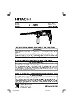
DISASSEMBLING

ASSEMBLING

Do the reverse of the disassembling steps.
Note:
When assembling Ring spring 28 to
Tool holder complete;
*Be careful not to position the end of the
  spring in either of the side holes on Tool
  holder complete.
*Use Piston cylinder as a jig as illustrated
  in Fig. 23.

Fig. 21

Fig. 22

5) Ring spring 28 can be pulled off from Tool holder complete when completely
    removed from the groove (Fig. 20).
    Note: Ring spring 28 will be damaged or deformed in the steps 4) and 5).
               Be sure to replace damaged/deformed Ring spring 28 when
               assembling Tool holder section
.
6) Remove Impact bolt section from Tool holder complete by striking Tool holder
    complete against workbench (Fig. 21).
7) Disassemble Impact bolt section as illustrated in Fig. 22.

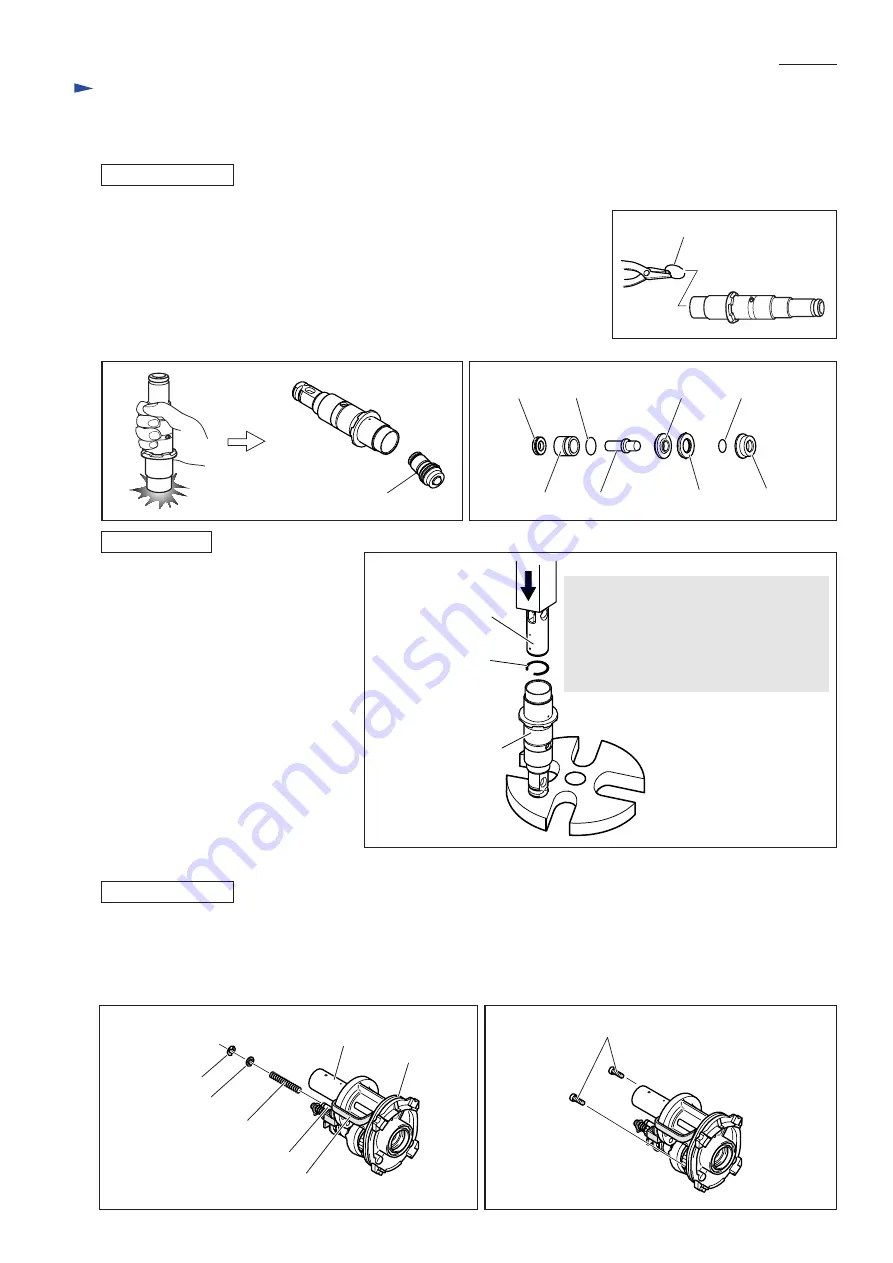
[3] -6. Swash Bearing Section

DISASSEMBLING

Impact bolt section

X ring 9 O ring 16

Ring 10

O ring 9

Sleeve 9 Impact bolt

Cushion ring 13 O ring case

Fig. 23

Piston cylinder as 
an assembling jig 

Note:
Never use the Piston cylinder built-in the
machine as the jig because it is scratched
when inserted in Tool holder complete.
Be sure to have an extra Piston cylinder
as a jig for the application.

Ring spring 28

Tool holder complete

1) Remove Inner housing from Gear housing (Fig. 14 in page 6).  If Ball bearing 606ZZ remains fixed in Gear housing,
    See page 9 for removal.  Remove Inner housing from Tool holder section (Fig. 15 in page 6).
2) Remove Stop ring E-4, Flat washer 5 and Compression spring 6 from the pin of Inner housing (Fig. 24).
3) Remove two M4x12 Hex socket head bolts that fasten Bearing retainer to Inner housing (Fig. 25).

Fig. 24

Fig. 25

Inner housing

Ring spring 28

Fig. 20

Fat washer 5

Compression spring 6

Stop ring E-4

Pin of Inner housing

Piston cylinder

Change plate

Hex socket head bolts M4x12

Summary of Contents for BHR240

Page 1: ...e Net Weight kg lbs Grip Assembly 1 set Depth Gauge Stopper Pole 1 pc SDS Plus bits Taper shank T C T bits Taper shank adapter Cotter Drill chuck assembly Chuck adapter Drill chuck S13 Bull points Dus...

Page 2: ...rmature holder 32 Fixing Tool holder Removing installing Ring spring 19 for modular use with 1R003 1R212 Tip for retaining ring pliers Installing Oil seal 25 1R232 Pipe 30 Removing Oil seal 25 1R252 R...

Page 3: ...older comp 28 X ring 9 Inner circumference Surface that contacts Tool holder comp 32 Sleeve 9 31 Ring 10 Surface that contacts Cushion ring 13 Whole surface 38 O ring 9 35 Whole surface 41 O ring 16 P...

Page 4: ...washer and Conical compression spring 21 29 Fig 5 ASSEMBLING Do the reverse of the disassembling steps Note Conical compression spring 21 29 and Ring spring 19 are not reversible when assembled to To...

Page 5: ...lace the provisionally assembled Change lever within the area A of Gear housing Fig 8 and insert into the Change lever installation hole Change lever cannot be inserted completely in this step 4 Pushi...

Page 6: ...ction Figs 3 4 5 in page 4 and Change lever Figs 7 8 2 Separate Gear housing from Motor housing Fig 12 Remove Armature from Gear housing Fig 13 3 Remove the assembly of Tool holder section and Inner h...

Page 7: ...trated in Fig 17 3 Clamp Tool holder complete using Vise and 1R038 as illustrated in Fig 18 4 Insert a slotted screwdriver between Ring spring 28 and O ring case through the side hole of Tool holder I...

Page 8: ...g 22 3 6 Swash Bearing Section DISASSEMBLING Impact bolt section X ring 9 O ring 16 Ring 10 O ring 9 Sleeve 9 Impact bolt Cushion ring 13 O ring case Fig 23 Piston cylinder as an assembling jig Note N...

Page 9: ...he rear dead center position Inner housing Swash bearing section Fig 28 Fig 29 Fig 30 6 Remove Ball bearing 606ZZ from Gear housing complete using the removed Swash bearing section as a jig as follows...

Page 10: ...ASSEMBLING 1 Assemble Swash bearing section using 1R034 as illustrated in Fig 33 Note 1 Be sure to put Flat washer 8 in place or Bearing retainer will be clamped between Ball bearing 608ZZ and Helica...

Page 11: ...ig 38 assemble Change plate to Inner housing and Clutch cam to Cam shaft at the same time Put Spur gear 10 and Compression spring 7 through Cam shaft and secure them with Retaining ring S 7 Put Compre...

Page 12: ...5 Face 34mm side to Oil seal 25 in Gear housing complete 1R164 Gear Housing Complete 1 Pass F R change lever s tab through switch cover left in Fig 42 2 Mount switch cover to switch by fitting the pro...

Page 13: ...Circuit diagram P 13 14 Yoke Unit Heat Sink F E T Terminal End bell Complete Color index of lead wires sheath Black Red Blue Fig D 1 Yellow Switch Tape to bundle the lead wires...

Page 14: ...following lead wires with band FET s lead wires black blue yellow Switch s lead wire red Rib A FET Rib C Route he following lead wire between rib B and rib C Switch s lead wires black and red FET s l...

Reviews: