P
8
/ 1
0
R
epair
[3] DISASSEMBLY/ASSEMBLY
[3]-4. Front Base, Base, Foot (cont.)
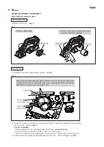
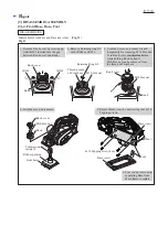
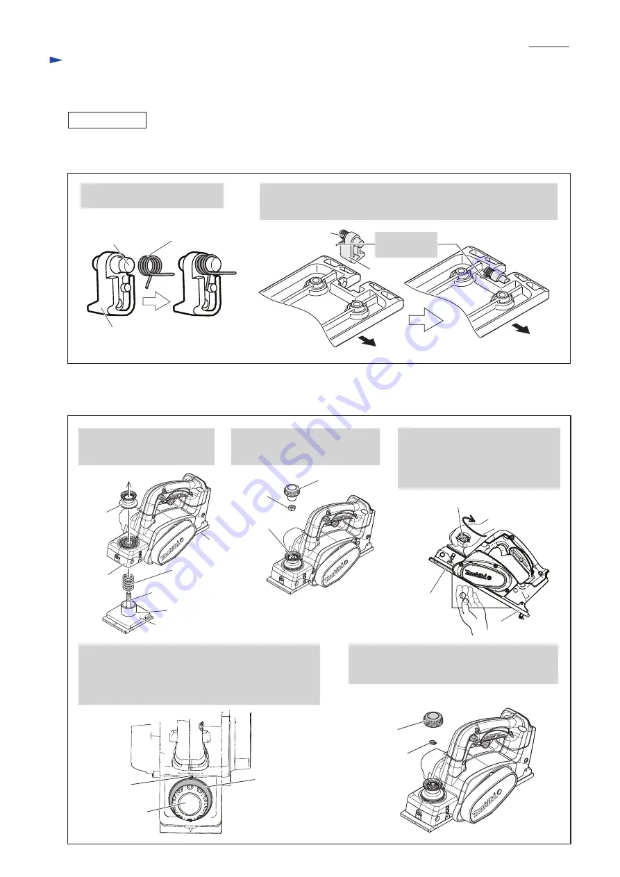
ASSEMBLING
Fig. 12
(1) Assemble Foot to Base (rear) before assembling Base to Main frame. (
Fig. 12
)
Assemble Base with Foot to Main frame by taking the disassembling step in reverse. (Refer to
Fig. 11
)
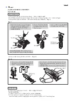
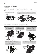
(2) Assemble Font base to Main frame. Then adjust the planing depth to zero. (
Fig. 13
)
Fig. 13
3. Assemble Front base to pass
its Threaded pole through
Main frame and Knob.
7. Assemble Retaining ring S-8 to Threaded pole
of Front base.
And install Knob cover by pressing to Knob.
4. Set M10 Hex nut to Threaded
pole of Front base. And engage
Knob cover with M10 Hex nut.
5. Turn Knob cover
clockwise
until
the surfaces of Front base and
Base contact the rule completely.
Planing depth will be set at the
zero level by the above adjustment.
Base
Base
1. Pass Long pin of Foot through
Torsion spring 7.
2. Facing Torsion spring 7 side to the opposite side of Belt cover side,
assemble Foot to Base (rear) with putting Torsion spring’s tail
on the Base.
Foot
Torsion spring 7
Long pin
of Foot
Belt cover side
Belt cover side
Torsion spring 7
Hook this tail
with Base.
Front base
Knob
M10
Hex nut
Rubber packing
Compression
spring 18
Knob cover
Front base
Main
frame
Threaded pole
Threaded pole
Knob cover
Retaining
ring S-8
6. While holding M10 Hex nut on Threaded pole of
Main frame with Knob cover functioning as Socket
wrench temporarily, align the indication "0" on Knob
to the triangle mark on Main frame.
And them, remove Knob cover.
Knob cover
Triangle
mark
0
Knob
Knob cover
Foot


