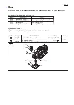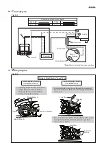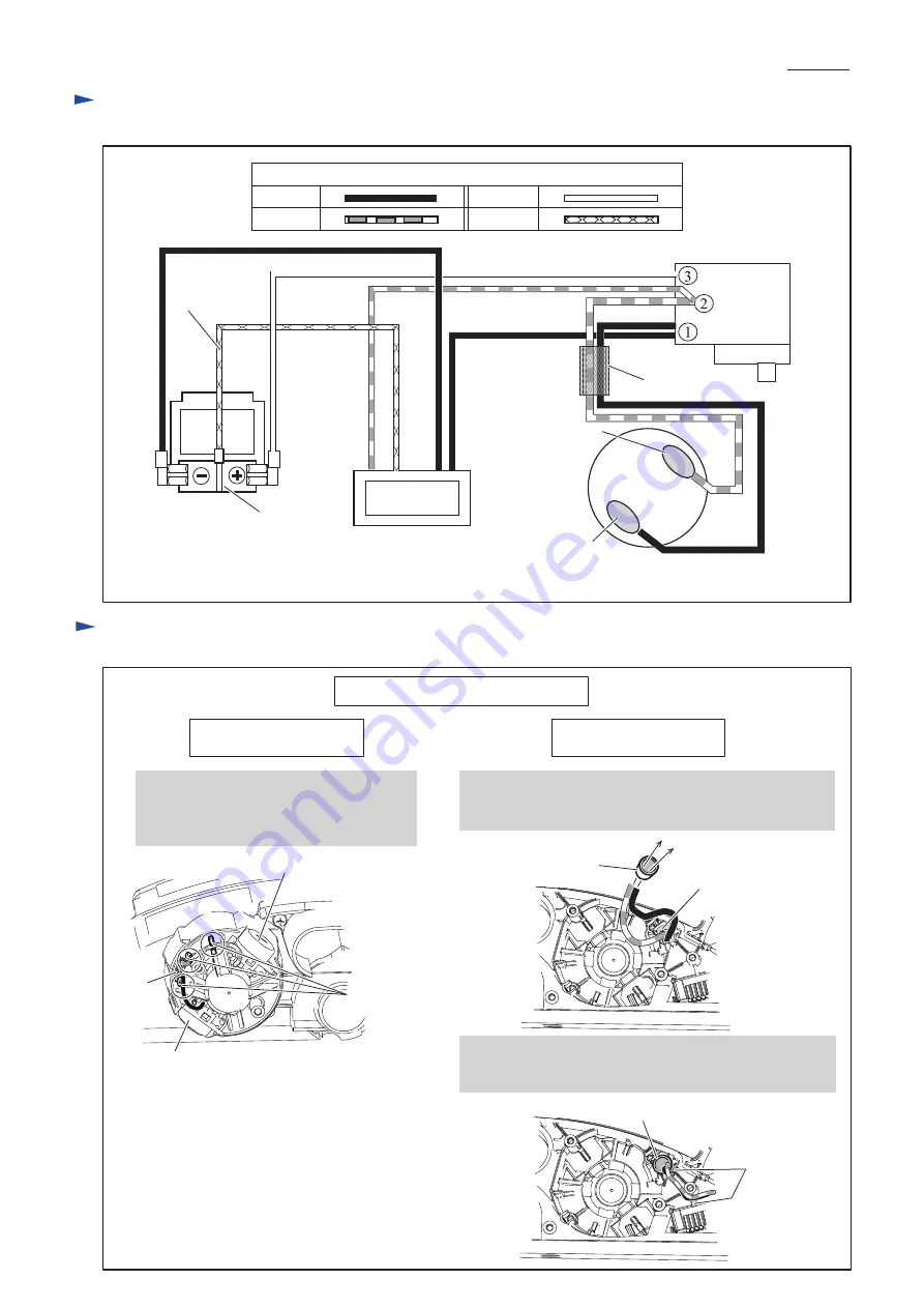
C
ircuit diagram
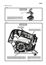
W
iring diagram
P
9
/ 1
0
White
Yellow
Color index of lead wires' sheath
Black
Red
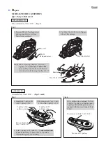
Base
Base
Brush holder A
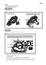
2. Pass Brush holder's lead wires through the opening of
Motor housing. Pass their lead wires through Line filter
if it is used.
3. Place Line filter into Motor housing if Line filter is used.
And tightening Brush holder's Lead wires, put them
into Lead wire holders.
Motor housing viewed
from
Rear cover
side
Motor housing, viewed
from
Bracket
side
Brush holder A
*
Line filter
Motor
Housing
Controller
Terminal
AS
Switch
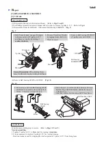
Wiring of Brush Holder's Lead Wire
1. Tightening Brush Holder's Lead Wires
and put them in Lead wire holders.
And guide them to inside of Motor
housing through the opening.
Brush holder B
Brush holder B
Opening
Fig. D-1
Fig. D-2
Lead wire holders
Line filter
Line filter
Opening
Lead wire
holders
*Line
filter is not used for some countries.


