background image

 7

7

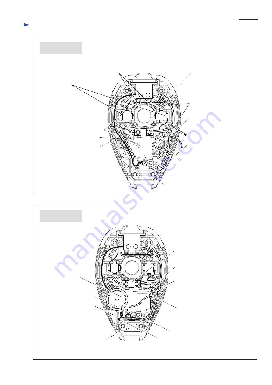
Fig. D-3

Fig. D-4

W

iring  diagram

Connect receptacles
with Brush holders
as illustrated.

Route Lead wires (black, white) between
rib A and rib B. 
Do not hook any Lead wires to the tops of 
the ribs. 

rib A

rib B

Noise suppressor

Fix lead wires (black)
to Brush holders with 
these Lead wire holders.

Fix lead wires (red) for Switch
with these Lead wire holders.

Put the slack portion of Lead wires 
(red, white) in the space here.

Put the slack portion of Lead wires 
(white) for Noise suppressor in the 
space here.

Fix Lead wire (white) with 
Lead wire holders.

Fix Lead wire (red) with Lead 
wire holder here.

Fix Field Lead wire (red) with 
the lowest Lead wire holder here.

Terminal block

rib C

boss for Tapping screw

Controller

Strain relief

Fix Controller Lead wire (white) 
with Lead wire holder here and
connect Terminal block.

Fix Controller Lead wire (red) 
with Lead wire holder here. 

Fix Controller Lead wire (red) 
with Lead wire holder. 

Insert Connector for Lead wire (red) between
rib C and Strain relief, and route the Lead wire (red)
between Strain relief and boss for Tapping screw. 

BO5031 before
inserting Controller

BO5031 after
inserting Controller

Note: Some specifications do not have Noise suppressor.

Summary of Contents for BO5030

Page 1: ...0 160 50 60 3 0 80 160 50 60 Continuous Rating W Voltage V Cycle Hz Input Output Max Output W Current A Sanding strokes spm min 1 Specification Model 153 6 123 4 7 8 153 6 Dimensions mm Width W Height...

Page 2: ...ver from the discharge nozzle of Skirt to hold Fan 88 linked with Armature shaft Fig 4 and remove M4x16 Pan head screw from the locked Armature shaft Bearing box cover Ball bearing 6202DDW and Flat wa...

Page 3: ...use 1R269 with waterpump pliers to remove Ball bearing 629DDW from Armature shaft Fig 11 Note The clearances between Ball bearing 607DDW and Insulation washer and Ball bearing 629DDW and Washer 9 are...

Page 4: ...Skirt and to set Skirt set in place in reassembling Fig 13 Fit Brake ring into Skirt set as illustrated in Fig 14 Repair P 4 7 3 DISASSEMBLY ASSEMBLY cont Fig 13 Fig 12 Fig 14 ASSEMBLING dust exit of...

Page 5: ...own is used for some countries Blue is used for some countries Connector is used instead of Terminal block for some countries Noise suppressor It is not used for some countries Noise suppressor It is...

Page 6: ...ders Brush holder Noise suppressor Fix lead wires red for Switch with these Lead wire holders Note Some specifications do not have Noise suppressor BO5030 Specifications with Terminal block BO5030 Spe...

Page 7: ...ace here Fix Lead wire white with Lead wire holders Fix Lead wire red with Lead wire holder here Fix Field Lead wire red with the lowest Lead wire holder here Terminal block rib C boss for Tapping scr...

Reviews: