P 26 / 28
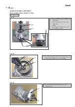
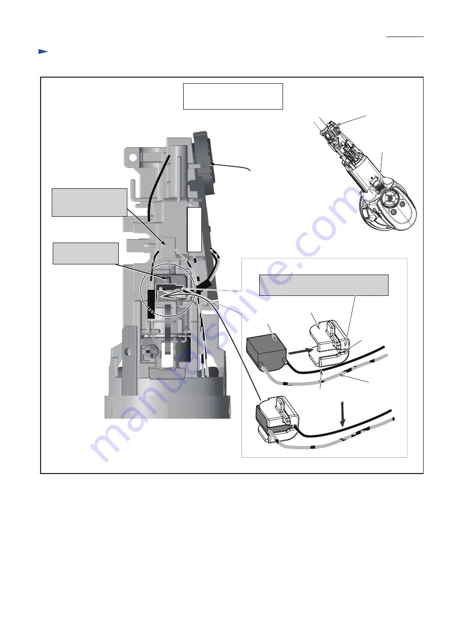
Fig. D-5
W
iring diagram
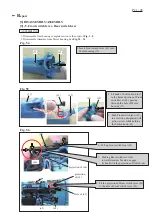
Switch knob
Pick up coil
closed groove
portion
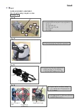
Lead wire
(white)
Lead wire (black)
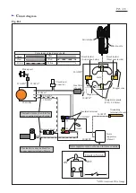
Dial of
Controller
Dial of
Controller
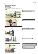
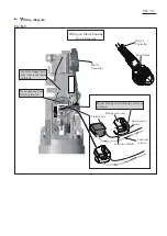
Wiring on Motor housing
Switch Knob side
Pick up coil cover
Mount Pick up coil to Pick up coil cover
as drawn.
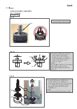
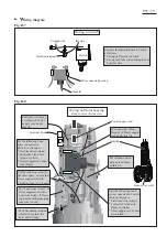
Put Field magnet lead
wire (red) to the inside
of this rib.
Do not put any Lead
wires on this rib.

