background image

Models No.

 Description

PRODUCT

T

ECHNICAL INFORMATION

P  1/

9

BTD141

Cordless Impact Driver

C

ONCEPT AND MAIN APPLICATIONS

S

pecification

S

tandard equipment

O

ptional  accessories

Note:

 The standard equipment for the tool shown above may differ by country.

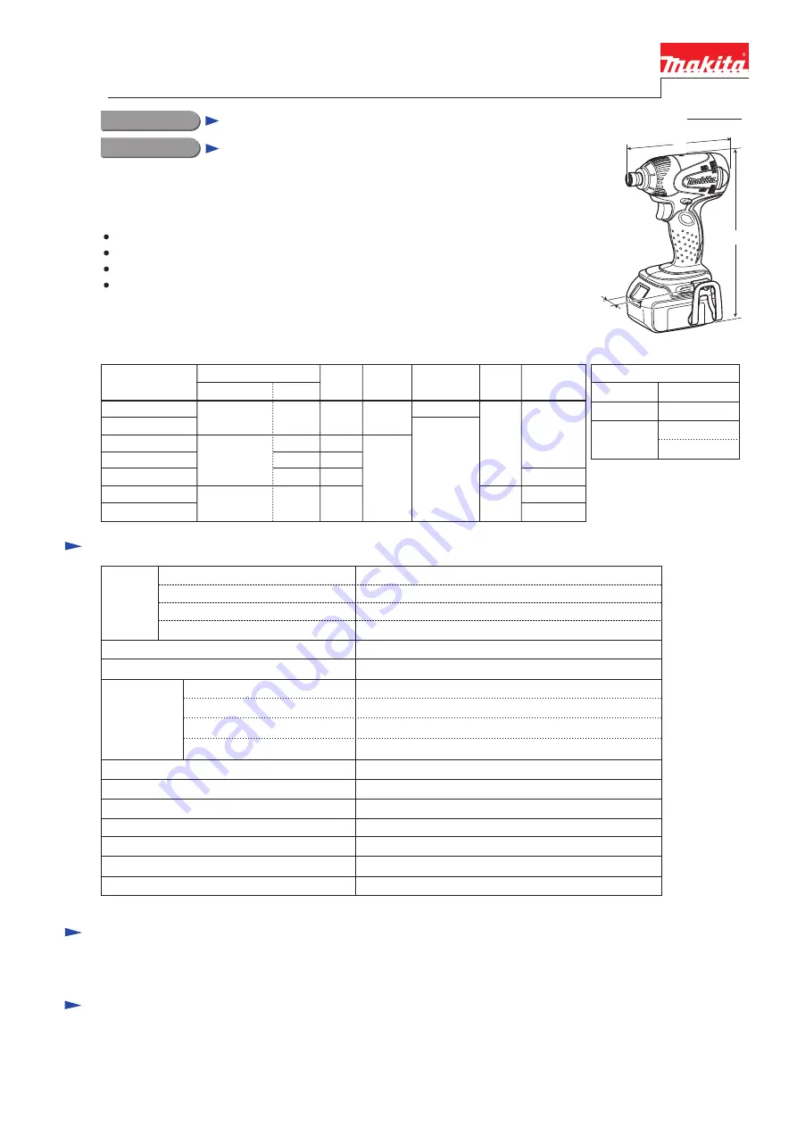
Model BTD141 has been developed as a successor model of BTD140.
Additionally to the same advantages as BTD140, Model BTD141 features:
   1.5Ah Li-ion battery BL1815 can be used.
   One-touch bit installation
   Compact hammer case cover
   Phosphorescent bumper that glows blue in dark places

See the product variation list above.

Battery

No load speed: min.-

1

=rpm

Impacts per min.: min.-

1

=ipm

Max. fastening torque

*

: N.m (kgf.cm/ in.lbs)

Charging time: min.

Capacities

Electric brake

Reverse switch
Net weight [with BL1815/ BL1830]: kg (lbs)

Variable speed control by trigger

Capacity: Ah
Cell

Voltage: V

18V

0 - 2,300

0 - 3,200

150 (1,530/ 1,330)

Standard bolt
High tensile bolt

Machine screw

Driving shank

M5 - M14 (3/16 - 9/16")

M5 - M12 (3/16 - 1/2")

Coarse thread screw

22 - 125mm (7/8 -  4-7/8")

M4 - M8 (5/32 - 5/16")

Yes
Yes
Yes

1.3/ 1.5 (2.8/ 3.3)

1.5/ 3.0 (battery BL1815/ BL1830) 

Li-ion

220

approx. 15/ 22 with DC18RA

6.35mm (1/4") Hex

This product is available in the following variations.

BTD141RFE

BTD141Z
BTD141ZK

BTD141RFE3
BTD141RFEW
BTD141RHE
BTD141RHEW

BL1830

(Li-ion 3.0Ah)

No

DC18RA

No

Model No.

type

quantity

Charger

No

Yes

Belt

clip

1
2

No

Battery

cover

Yes

No

Plastic

carrying case

2
3

2

2

No

BL1815

(Li-ion 1.5Ah)

Battery

Makita-blue

white

Makita-blue

white

Housing

color

1

1

Phillips bits
Socket bits
Bit piece

Li-ion Battery 1830
Li-ion Battery 1815
Fast charger DC18RA

Charger DC24SA

 (for North America only)

Charger DC24SC

 (for all countries except North America)
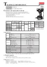
Dimensions: mm (")

Width (W)

Height (H)

Length (L)

145 (5-3/4)

79 (3-1/8)

235 (9-1/4)

*2

217 (8-1/2)

*1

*1: with Battery BL1815
*2: with Battery BL1830

W

L

H

(with Battery BL1830)

Max output (W)

*

C

atalog value (torque at 3 seconds after seating, when fastening M14 high tensile bolt)

Summary of Contents for BTD141

Page 1: ... 330 Standard bolt High tensile bolt Machine screw Driving shank M5 M14 3 16 9 16 M5 M12 3 16 1 2 Coarse thread screw 22 125mm 7 8 4 7 8 M4 M8 5 32 5 16 Yes Yes Yes 1 3 1 5 2 8 3 3 1 5 3 0 battery BL1815 BL1830 Li ion 220 approx 15 22 with DC18RA 6 35mm 1 4 Hex This product is available in the following variations BTD141RFE BTD141Z BTD141ZK BTD141RFE3 BTD141RFEW BTD141RHE BTD141RHEW BL1830 Li ion ...

Page 2: ...ead 9 5 Attaching to 1R223 when disassembling Hammer case 1R232 Pipe 30 Supporting Anvil to remove Sleeve easily 1R288 Screwdriver Magnetizer Removing Steel balls 1R291 Retaining Ring S R Pliers Disassembling Sleeve 134847 1 Socket 30 78 Disassembling Hammer case 134848 9 Socket 32 50 Fixing Bearing box when removing Hammer case Use for Item No Description Portion to lubricate Anvil 16 Hammer case...

Page 3: ...ght PT3x16 Tapping screws 4 Remove the assembly of Hammer section and Motor section from Housing L then separate Hammer section from Motor section DISASSEMBLING Rear cover Tapping screw PT3x16 2 pcs Hammer case cover Hammer case complete Belt clip Fig 2 Screw M4x12 Fig 4 1 2 A Brush holder section Viewed from A Carbon brush Carbon brush Torsion spring 1 Shift the tail of Torsion spring onto the no...

Page 4: ...portion of Hammer case complete Then by turning Socket 30 78 clockwise with 1R223 and 1R224 Hammer section can be disassembled as illustrated to right in Fig 5 Fig 5 Hammer section 1R223 1R224 Socket 30 78 1R041 Vise Socket 32 50 1R041 Bearing box Internal gear 51 O ring 40 Bearing box Hammer mechanism Hammer case complete Hammer case complete Bit holder section 9 Remove Spindle Compression spring...

Page 5: ... Internal gear 51 ASSEMBLING Fig 11 Fig 10 Internal gear 51 Bearing box O ring 40 stepped end Internal gear 51 O ring 40 Bearing box Hammer mechanism Hammer case complete four grooves on the inside surface locking claw of Hammer case cover Bumper depressed portion locking protrusion 6 When assembling Bumper to Hammer case cover 1 Match the depressed portions of Bumper to the locking claws of Hamme...

Page 6: ...arate the assembly of Armature and Yoke unit from the machine Refer to 1 to 4 of 3 1 Disassembling Hammer Section 2 Put the assembly of Yoke unit and Armature on work bench so that the drive end of the Armature touches work bench Then separate Yoke unit from armature by pressing it down towards work bench Fig 17 DISASSEMBLING 1R232 Anvil Hammer case complete Sleeve Ring spring 11 Sleeve Important ...

Page 7: ... of Armature that is pulled strongly by the magnet force of Yoke unit Fig 18 Fig 19 ASSEMBLING 3 Assemble Motor section and Hammer section to Housing L as described in Figs 20 21 Your fingers can be pinched and injured Wrong Correct Wrong Correct notch Fig 20 notch Housing L projection Hammer case side Brush holder complete must be so mounted that its flat portion is 90 degrees to the edge of Hous...

Page 8: ... in Fig D 2 is Carbon brush section viewed from A Correct Wrong Lead wire of Carbon brush Lead wire correctly routed Torsion spring tail of Torsion spring tail of Torsion spring Circuit diagram Color index of lead wires sheath Black White Red Orange Blue LED Light circuit Switch Brush holder complete Terminal Connector Wiring diagram A Route the lead wire of Carbon brush through this outside slot ...

Page 9: ...it Lead wires red and black from Terminal to Connector small Lead wire blue from Switch to Connector small 2 1 Lead Wires of LED Lead wire holder Light circuit Fit the corner of LED in this corresponding corner of Housing L As illustrated below fix the two Lead wires black white of LED with Lead wire holders and route them between the pin and the boss Connector large Connector small Lead wire hold...

Reviews: