background image

P  

4

/

9

R

epair

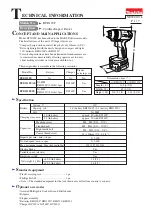
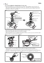
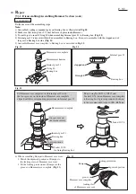
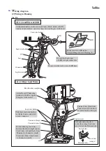
[3] -1. Disassembling/Assembling Hammer Section (cont.)

top of cam groove
on Spindle

Steel ball 5.6

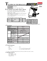
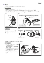
6) Install 1R346 on R045, and set them on Hammer mechanism as illustrated in Fig. 6.
    Then turn the handle of 1R045 clockwise to lower Hammer to the full.
7) Align the notch in Hammer with the top of the cam groove on Spindle. 
    Then take Steel ball 5.6 (2 pcs) out of Spindle using tweezers or a slotted screwdriver magnetized with 1R288. (Fig. 7)
8) Remove 1R045 by turning the handle counterclockwise.

Fig. 7

Hammer

Spindle

1R346

1R045

Fig. 6

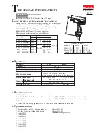
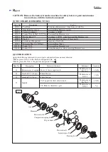
5) Attach a pair of 1R041 to vise.   Fix Socket 32-50 in vise securely.   Then put Hammer section on Socket 32-50
    while fitting the hexagonal portion of Bearing box in Socket 32-50.  Fit Socket 30-78 over the hexagonal portion of
    Hammer case complete.  Then, by turning Socket 30-78 clockwise with 1R223 and 1R224, Hammer section can be
    disassembled as illustrated to right in Fig. 5.

Fig. 5

Hammer section

1R223

1R224
Socket 30-78

1R041

Vise

Socket 32-50

1R041

Bearing box

Internal gear 51
O ring 40

Bearing box

Hammer mechanism

Hammer case complete

Hammer case complete

Bit holder section

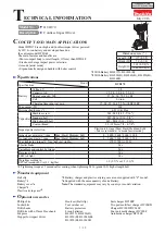
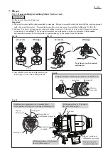
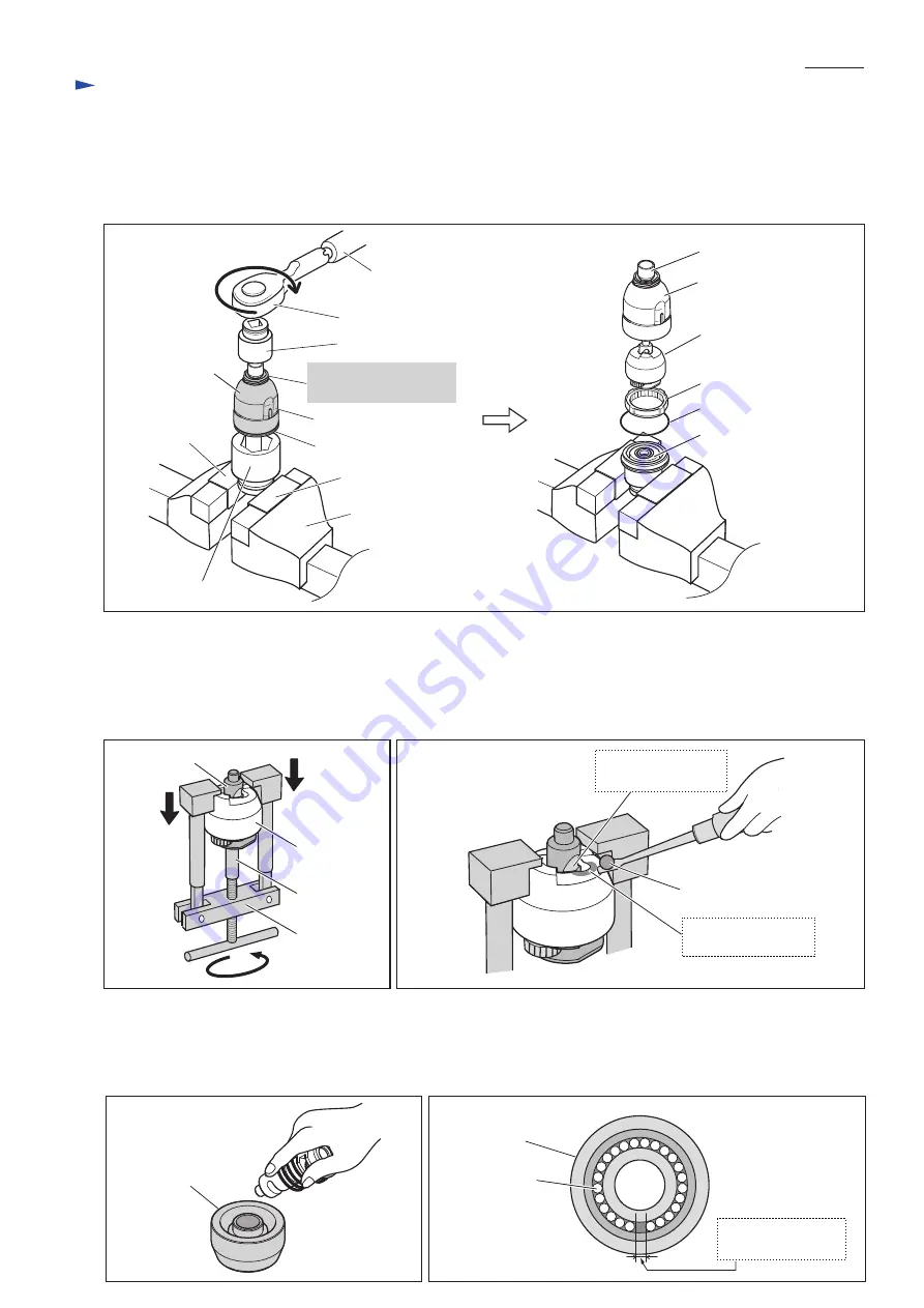
  9) Remove Spindle, Compression spring 45 and Cup washer 14 from Hammer as illustrated in Fig. 8.
      Important: Be sure to lower the Hammer side so that Steel balls in Hammer cannot fall down and scatter.
10) Steel ball 3.5 can now be removed from Hammer.    There are twenty-four 3.5 Steel balls in the groove on the inside
      of Hammer. (As illustrated in Fig. 9, the groove is designed to have a space equivalent to one 3.5 Steel ball.)

Fig. 9

Hammer

Steel ball 3.5

(24 pcs)

space equivalent to
one 3.5 Steel ball

Fig. 8

Hammer

notch for
Steel ball insertion

Fit Socket 30-78 over
this hexagonal portion.

Summary of Contents for BTD141

Page 1: ... 330 Standard bolt High tensile bolt Machine screw Driving shank M5 M14 3 16 9 16 M5 M12 3 16 1 2 Coarse thread screw 22 125mm 7 8 4 7 8 M4 M8 5 32 5 16 Yes Yes Yes 1 3 1 5 2 8 3 3 1 5 3 0 battery BL1815 BL1830 Li ion 220 approx 15 22 with DC18RA 6 35mm 1 4 Hex This product is available in the following variations BTD141RFE BTD141Z BTD141ZK BTD141RFE3 BTD141RFEW BTD141RHE BTD141RHEW BL1830 Li ion ...

Page 2: ...ead 9 5 Attaching to 1R223 when disassembling Hammer case 1R232 Pipe 30 Supporting Anvil to remove Sleeve easily 1R288 Screwdriver Magnetizer Removing Steel balls 1R291 Retaining Ring S R Pliers Disassembling Sleeve 134847 1 Socket 30 78 Disassembling Hammer case 134848 9 Socket 32 50 Fixing Bearing box when removing Hammer case Use for Item No Description Portion to lubricate Anvil 16 Hammer case...

Page 3: ...ght PT3x16 Tapping screws 4 Remove the assembly of Hammer section and Motor section from Housing L then separate Hammer section from Motor section DISASSEMBLING Rear cover Tapping screw PT3x16 2 pcs Hammer case cover Hammer case complete Belt clip Fig 2 Screw M4x12 Fig 4 1 2 A Brush holder section Viewed from A Carbon brush Carbon brush Torsion spring 1 Shift the tail of Torsion spring onto the no...

Page 4: ...portion of Hammer case complete Then by turning Socket 30 78 clockwise with 1R223 and 1R224 Hammer section can be disassembled as illustrated to right in Fig 5 Fig 5 Hammer section 1R223 1R224 Socket 30 78 1R041 Vise Socket 32 50 1R041 Bearing box Internal gear 51 O ring 40 Bearing box Hammer mechanism Hammer case complete Hammer case complete Bit holder section 9 Remove Spindle Compression spring...

Page 5: ... Internal gear 51 ASSEMBLING Fig 11 Fig 10 Internal gear 51 Bearing box O ring 40 stepped end Internal gear 51 O ring 40 Bearing box Hammer mechanism Hammer case complete four grooves on the inside surface locking claw of Hammer case cover Bumper depressed portion locking protrusion 6 When assembling Bumper to Hammer case cover 1 Match the depressed portions of Bumper to the locking claws of Hamme...

Page 6: ...arate the assembly of Armature and Yoke unit from the machine Refer to 1 to 4 of 3 1 Disassembling Hammer Section 2 Put the assembly of Yoke unit and Armature on work bench so that the drive end of the Armature touches work bench Then separate Yoke unit from armature by pressing it down towards work bench Fig 17 DISASSEMBLING 1R232 Anvil Hammer case complete Sleeve Ring spring 11 Sleeve Important ...

Page 7: ... of Armature that is pulled strongly by the magnet force of Yoke unit Fig 18 Fig 19 ASSEMBLING 3 Assemble Motor section and Hammer section to Housing L as described in Figs 20 21 Your fingers can be pinched and injured Wrong Correct Wrong Correct notch Fig 20 notch Housing L projection Hammer case side Brush holder complete must be so mounted that its flat portion is 90 degrees to the edge of Hous...

Page 8: ... in Fig D 2 is Carbon brush section viewed from A Correct Wrong Lead wire of Carbon brush Lead wire correctly routed Torsion spring tail of Torsion spring tail of Torsion spring Circuit diagram Color index of lead wires sheath Black White Red Orange Blue LED Light circuit Switch Brush holder complete Terminal Connector Wiring diagram A Route the lead wire of Carbon brush through this outside slot ...

Page 9: ...it Lead wires red and black from Terminal to Connector small Lead wire blue from Switch to Connector small 2 1 Lead Wires of LED Lead wire holder Light circuit Fit the corner of LED in this corresponding corner of Housing L As illustrated below fix the two Lead wires black white of LED with Lead wire holders and route them between the pin and the boss Connector large Connector small Lead wire hold...

Reviews: