P
4
/
18
R
epair
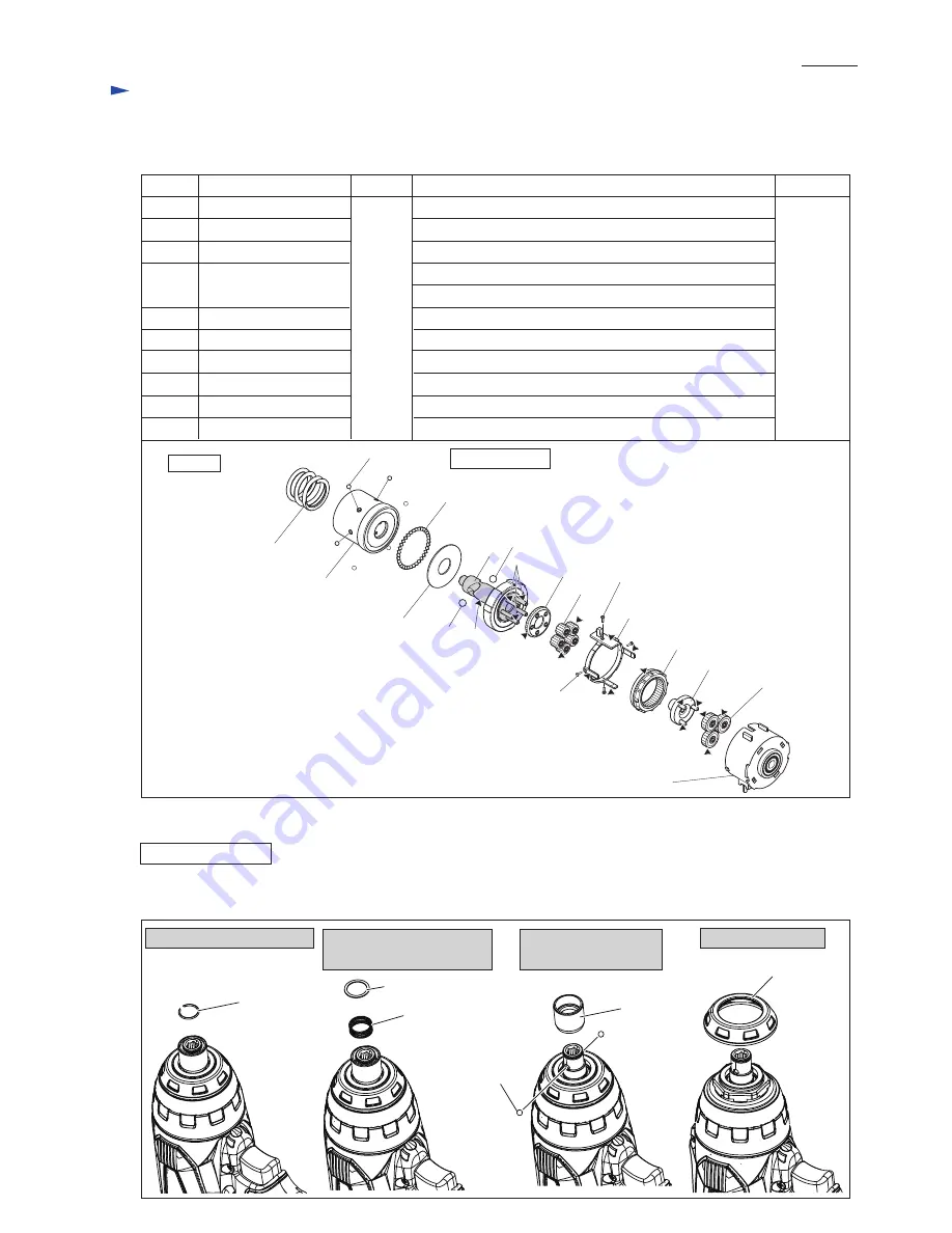
Apply
Makita grease N. No.2
to the following portions designated with the black triangle to protect
parts and product from unusual abrasion.
[2]-2 LUBRICATION
[3]-1 Impact Assembly, Anvil
(1) Disassemble Bit holder section and Bumper for attaching 1R224 (
Fig. 2, 3
).
1. Remove Ring spring 11. 2. Remove Flat washer 12,
Compression spring 13.
3. Remove Sleeve and
Steel ball 3.5 (2pcs.)
4. Remove Bumper.
Fig. 2
DISASSEMBLING
Bumper
Steel ball 3.5
Sleeve
Sleeve
Flat washer 12
Compression
spring 13
a little
62
58
57
58
57
Spur gear 41
Spur gear 14B
Teeth portion
Teeth portion
54
53
51
54
53 a
a: Spindle portion
b
b: Pins for Gears 57, 58
Pins for Gears 63
63
62
Spur gear 14A complete
63
Spur gear 21
Teeth portion
60
60
Change lever
The sliding area in Motor bracket
Pin 1.2
Pin 1.2
Motor bracket assembly
Compression
spring 22
Outer hammer
Flat washer 14
49
61
61
Internal gear 41
Groove portion where 4 pcs. of Pin 1.2 fit
Item No.
Description
Grease
Amount
Portion to lubricate
49
Steel ball 3 (6 pcs.)
whole portion
51
Steel ball 3 (34 pcs.)
whole portion
53
Steel ball 3 (34 pcs.)
whole portion
Spindle complete
Fig. 1A
Impact Section
Makita
grease N.
No.2


