P
8
/
18
R
epair
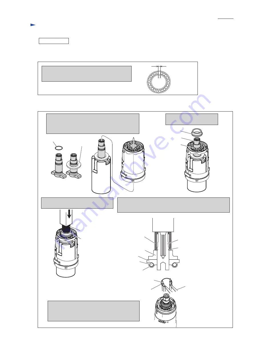
[3]-1 Impact Assembly, Anvil
(2) Assemble Cam A (
Fig. 10
)
.
ASSEMBLING
Note: The Space equivalent to one steel ball remains
on Cup washer when
22 pcs
. of Steel ball 3 are
correctly set on it.
(1) Put 22 pcs of Steel ball 3 to Cup washer (
Fig. 9
).
And then, assemble the Cup washer and Cam B to Gear case assembly (
Fig. 8
-5
).
Fig. 10
Fig. 9
Space equivalent
to one Steel ball
1R351
1R351
1R351
Cam A
2. Set Cam A to Cam B facing
its cam gear side to Cam B.
Cam B
Anvil
1. Assemble O ring 12.5 and Nylon washer 15 to Anvil.
Put Anvil on 1R351 while fitting its wings to
Shallow notch of 1R351.
And set Gear case assembly to the Anvil.
O ring 12.5
3. Set 1R390 on the Cam A and press it
with Arbor press until Cam A stops.
4. While expanding Retaining ring WR-15 with 1R291,
set the Retaining ring to tips of 1R003 with 1R212.
And mount the expanded Retaining ring WR-15
to the groove on Anvil.
Nylon
washer 15
Cam A
Cam A
Cam B
Steel ball 3
Cup washer
1R390
1R390
Anvil
Arbor press
Groove for
Retaining ring WR-15
Retaining Ring WR-15
1R291
1R003 attached
with 1R212
Note: Cam A must be mounted until the groove for Retaining ring
WR-15 on Anvil is reserved. Press 1R390 until the top surface
of Anvil comes to the same level of the top surface of 1R390.


