[3]-1 Impact Assembly, Anvil
ASSEMBLING
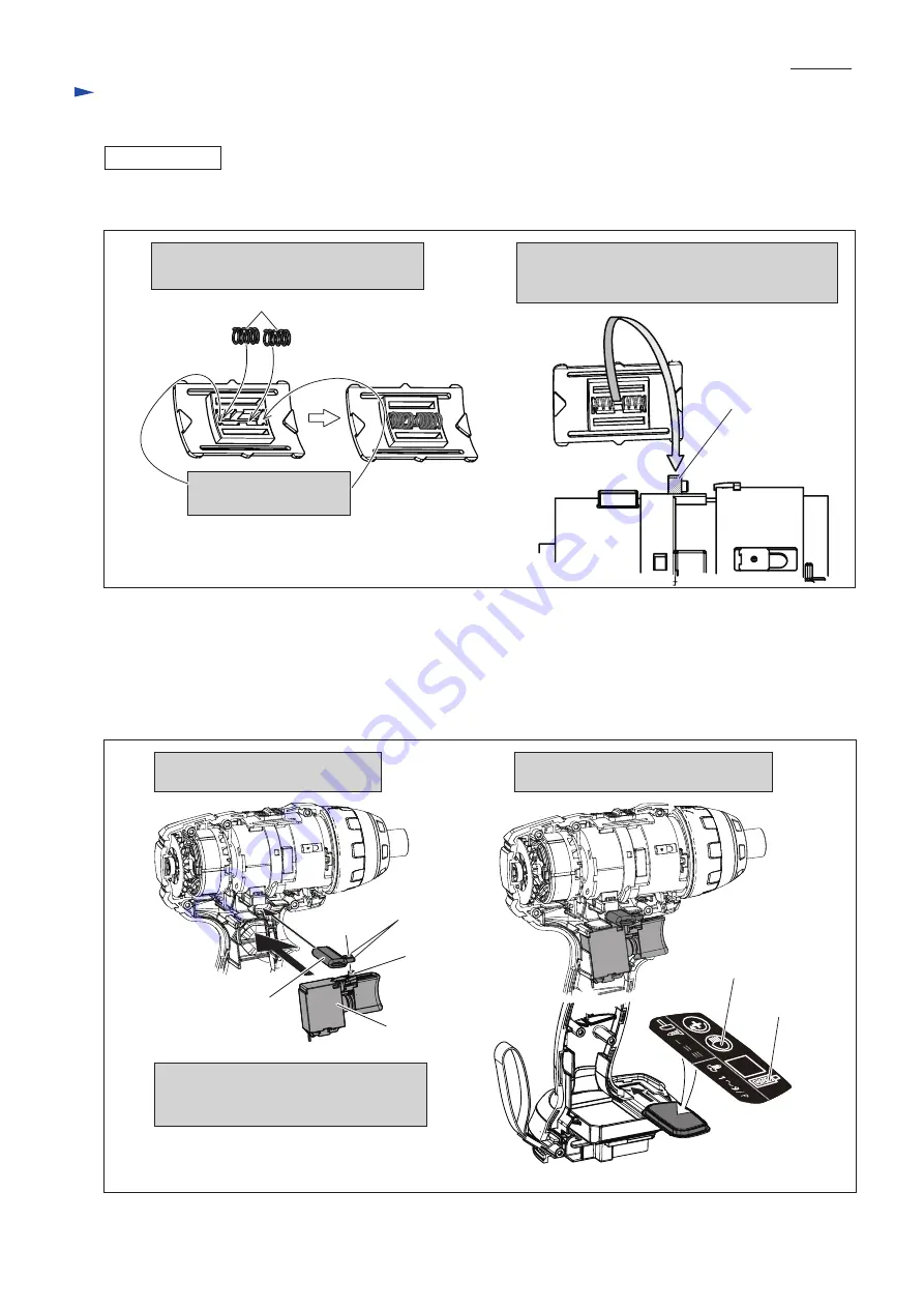
(8) Assemble Speed change lever to Impact assembly (
Fig. 16
).
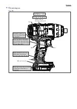
(9) Now, Impact assembly is assembled completely. And assemble Motor section (Rotor and Stator complete)
to the Impact assembly (
Fig. 4
-3
).
Mount 2 pcs of Switch unit to Motor bracket assembly and set the Impact assembly together with Motor section to
Housing L (
Fig. 4
-2
).
(10) Assemble F/R Change lever to Switch, and mount Switch plate complete to Housing L (
Fig. 17
).
Fig. 16
Fig. 17
1. Insert 2 pcs of Compression spring 3
to Speed change lever assembly.
2. Mount Speed change lever assembly by fitting
the space between two Compression springs to
Projection of Change lever.
Put end of Spring in this
frame.
Compression spring 3
Projection of
Change lever
(11) Tighten Hammer case assembly with Socket 32-50, 1R223 and 1R224 (
Fig. 3
).
Note; The fastening torque for Hammer case assembly is
15 - 20 N.m
.
F/R Change lever
Switch
3. Facing the symbols of “Job light” and
“Battery power display” to front side,
set Switch plate complete to Housing L.
1. Fit the projection of Switch to
fork portion of F/R change lever.
2. Set the Switch with F/R change lever
to Housing L.
Projection
of Switch
Prong of
F/R Change lever
Battery power
display
Job light
R
epair
P 1
2
/
18


