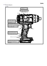
Route all of the Lead wires
within these ribs. Do not
let Lead wires cross the ribs
Fig. D-5
Wiring in Housing L
BTD141 18V
Controller
Terminal
Switch
Rib
Rib
Rib
Ribs on Controller
Switch units for
detecting work mode
Stator
Put slack portion of
Lead wires from Stator
in this place.
Route Lead wires of Switch
units for detecting work mode
and the Lead wires from Stator
between these Ribs.
Route Lead wires from Controller
to Terminal behind Ribs on
Controller.
C
ircuit diagram
P
18
/
18


