Models No.
Description
NEW TOOL
T
ECHNICAL INFORMATION
C
ONCEPTION AND MAIN APPLICATIONS
S
pecification
S
tandard equipment
O
ptional accessories
< Note > The standard equipment for the tool shown may differ from country to country.
P 1 / 9
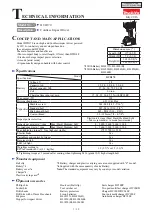
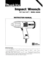
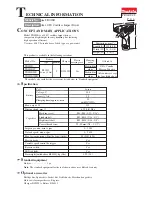
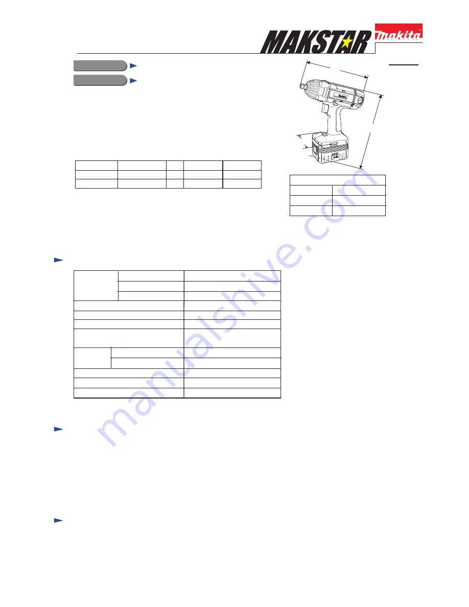
Dimensions : mm ( " )
Width ( W )
Height ( H )
Length ( L )
86 (3-3/8)
277 (10-7/8)
226 (8-7/8)
H
L
W
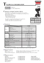
BTW201
24V Cordless Impact Wrench
The variations of this model are as listed below.
Model No.
Battery
Q'ty Type of cell
Charger
BTW201SH B2417 (1.7Ah) 1pc.
Ni-MH
DC24SA
BTW201SF
B2430 (3.0Ah) 1pc.
Ni-MH
DC24SA
No load speed : (min
-1
= rpm)
Blows per min : (min
-1
= bpm).
Drive shank : mm=( " )
Max. fastening torque
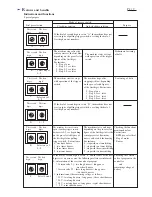
BPM. pre-selection system
Reverse switch
Capacity
Standard bolt
High tensile bolt
200 Nm
(2,040 kgf.cm, 1,770 in.lbs)
0 - 2,000
0 - 3,000
Square 12.7 (1/2)
M10 - M12 (3/8 - 1/2)
M10 - M16 (3/8 - 5/8)
Net weight including battery B2417
2.9Kg (6.3 lbs)
Yes
Yes
Battery
Voltage ( V )
Capacity (Ah)
Type of cell
Ni-MH
3.0
24
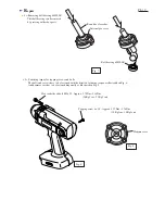
* Socket 19-52 ....................... 1 pc.
* Pin 4 ........................ 1 pc.
* O ring 24 ........................ 1 pc. ( Except North American market)
* Various Sockets
* Battery B2417 / 1.7 Ah
* Battery B2430 / 3.0 Ah
* Charger DC24SA
* ADP01 Interchangeable adapter
* ADP02 Refreshing adapter
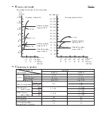
Model BTW201 can compete with the existing 360W class
AC tool, Mod.6904VH in max. fastening torque.
And its BPM. Pre-selection System prevents the over-tightening.