F
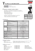
eatures and benefits
P 4 / 9
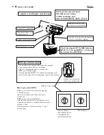
Indications and functions
0 1
2
3
4
5
6
7
8
9
A
B
C
D
E
F
0
1
2
3
4
5
6
7
8
9
A
0 - 9
B
Select any of
0 - 9
Select any of
0 - 9
0 1
2
3
4
5
6
7
8
9
A
B
C
D
E
F
0
1
2
3
4
5
6
7
8
9
C
0 1
2
3
4
5
6
7
8
9
A
B
C
D
E
F
0
1
2
3
4
5
6
7
8
9
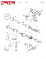
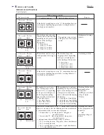
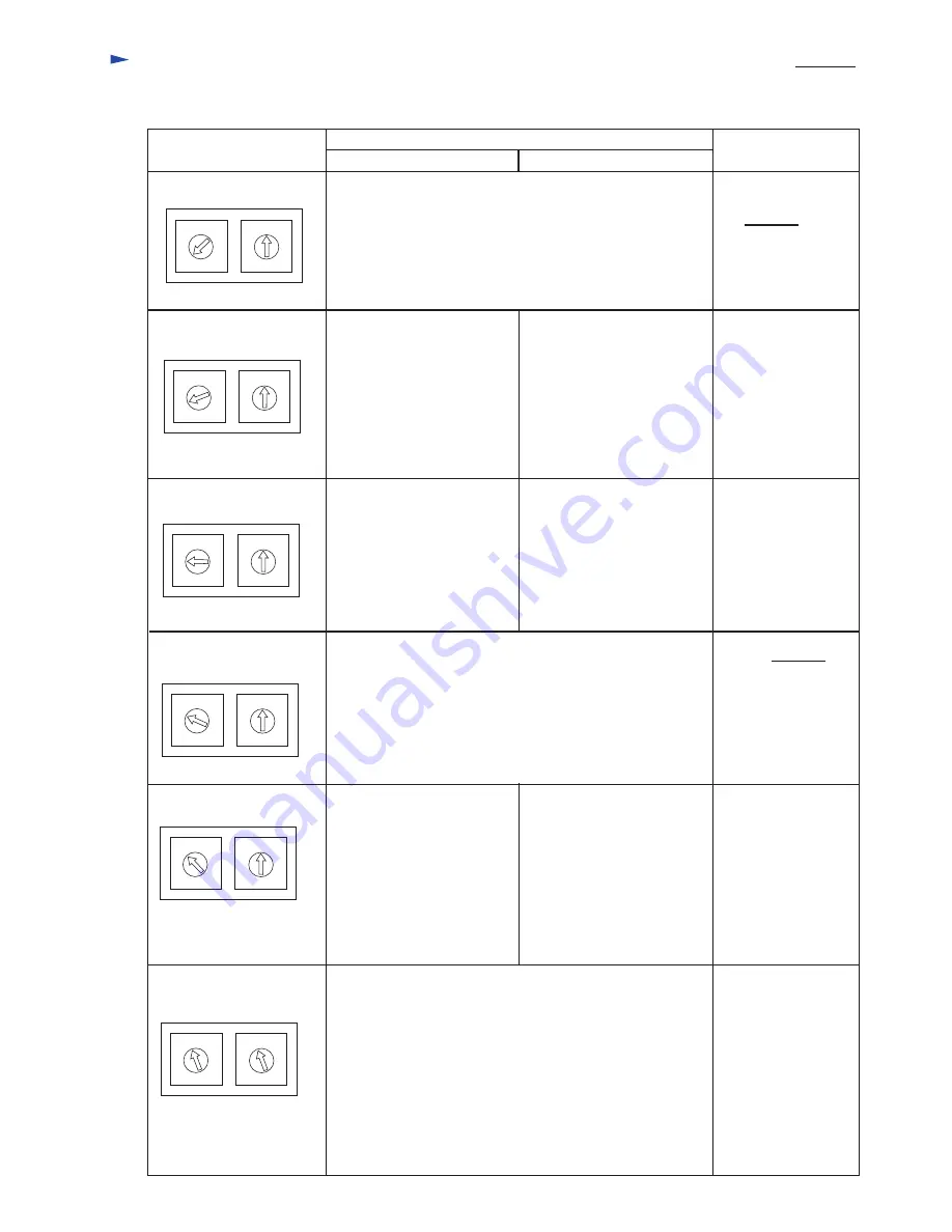
Special purpose
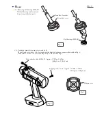
Dial pre-selection
Clockwise rotation
Anti-clockwise rotation
Mode of reverse switch
If the dial of second digit is set on "A", the machine does not
start in spite of pulling trigger switch, or setting the dial of
first digit on any numbers.
Purpose
The machine stops after the
sensor perceives the first blow,
depending on the pre-selected
figures of the first digit.
For instance,
0 : Stop at one
1 : Stop 0.1 sec. later
2 : Stop 0.2 sec. later
9 : Stop 0.9 sec. later
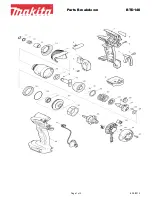
The machine starts or stops
with operation of the trigger
switch.
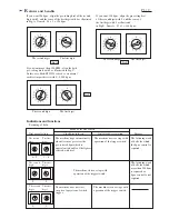
Preliminary fastening
of bolts
The machine starts or stops
with operation of the trigger
switch.
Loosening of bolts
The machine stops after
stopping its blow, depending
on the pre-selected figures
of the first digit. For instance,
0 : Stop at one
1 : Stop 0.1 sec. later
2 : Stop 0.2 sec. later
9 : Stop 0.9 sec. later
The second
digit
The first
digit
The second
digit
The first
digit
The second
digit
The first
digit
0 - 9
0 1
2
3
4
5
6
7
8
9
A
B
C
D
E
F
0
1
2
3
4
5
6
7
8
9
D
E
0 1
2
3
4
5
6
7
8
9
A
B
C
D
E
F
0
1
2
3
4
5
6
7
8
9
Select any of
0 - 9
The second
digit
The first
digit
The second
digit
The first
digit
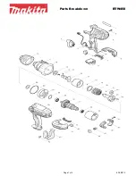
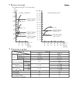
The machine does not start in
spite of pulling trigger switch,
but buzzers
0.2 sec. depending
on the pre-selected figure of
the first digit after pulling
trigger switch, . For instance,
0 : one time buzzer
1 : two times buzzer
2 : three times buzzer
9 : ten times buzzer
Checking the functions
mentioned below.
For instance
* BPM. pre-select dial
* Stop of motor
* Buzzer
F
0 1
2
3
4
5
6
7
8
9
A
B
C
D
E
F
0
1
2
3
4
5
6
7
8
9
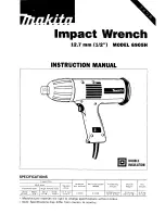
Select 0 and 1
The second
digit
The first
digit
If the dial of second digit is set on "D", the machine does not
start in spite of pulling trigger switch, or setting the dial of
first digit on any numbers.
The machine starts, and stops
depending on the pre-selected
figure of the first digit after the
sensor perceives how many
times you have hit the housing,
For instance,
0 : stop with one time hitting
1 : stop with two times hitting
2 : stop with three times hitting
9 : stop with ten times hitting
If the dial of second digit is set on "F" and the same of the first
digit is set on zero or one, the following matters are informed.
0 : information of the version code of program
* Version code 2.1 : two long buzzers - long pause,
- one short buzzer
* Version code 3.2 : three long buzzers - long pause,
- two short buzzers
1 : information of the remaining voltage as follows.
* 23 V : two long buzzers - long pause - three short buzzers
* 20 V : two long buzzers
* 18 V : one long buzzer - long pause - eight short buzzers
* 9 V : nine short buzzers
Checking the version
code of program in the
controller
and
remaining voltage of
battery