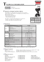
background image

P 7 / 9 

R

epair

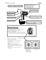
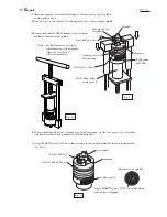
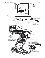
(2)Adjust the opening for steel ball inserting, to the cam groove  top of spindle
     as illustrated in Fig. 5.

Spindle

Cam groove  top
of spindle

Opening for steel 
ball inserting

Steel ball 5.6 x 2pcs.

Steel ball 4 x 25pcs.

Hammer

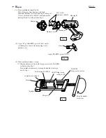
(3)Take off  2 pcs. of steel balls  5.6 with magnetic bar or tweezers from spindle.

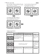
(4)Loosen the handle of 1R045 turning it anti-clockwise
     and remove hammer from spindle.

(5)When assembling, adjust the "opening for steel ball inserting", to the "cam groove  top" of spindle
     and insert steel ball 5.6 into hammer as illustrated in Fig. 5.

< Note > Set the hammer as per Fig.5A, 
               when removing it from spindle.
               Otherwise steel balls 4
               will fall off hammer.

Ball bearing 
6002LLB

1R165 Ring spring 
           setting tool B

Fig. 5

Fig. 5A

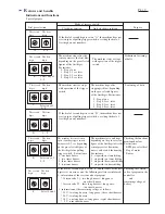
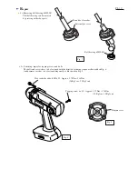
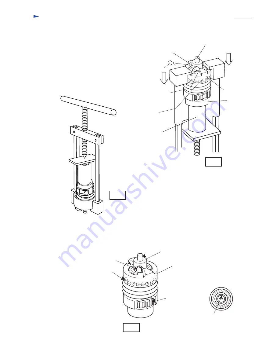
(6) Apply MAKITA grease N No.2 in small volume to the position marked with black triangle mark.
     See Fig. 6.   

(1) Spindle

(3) Steel ball 5.6 x 2

(2) Steel ball 4 x 25pcs.

Hammer

(4) Spur gear 24

Fig. 6

Bottom view of spindle

Apply MAKITA grease N No.2 in small volume
into the hole of spindle.

Summary of Contents for BTW201

Page 1: ... min 1 rpm Blows per min min 1 bpm Drive shank mm Max fastening torque BPM pre selection system Reverse switch Capacity Standard bolt High tensile bolt 200 Nm 2 040 kgf cm 1 770 in lbs 0 2 000 0 3 000 Square 12 7 1 2 M10 M12 3 8 1 2 M10 M16 3 8 5 8 Net weight including battery B2417 2 9Kg 6 3 lbs Yes Yes Battery Voltage V Capacity Ah Type of cell Ni MH 3 0 24 Socket 19 52 1 pc Pin 4 1 pc O ring 24...

Page 2: ...01 Long life DC motor with externally accessible brushes Aluminum hammer case with rubber cover Palm fitly soft grip with ergonomically shape for comfortable gripping 12 7mm 1 2 square drive Push button for reversing Variable speed control switch 0 1 2 3 4 5 6 7 8 9 A B C D E F 0 1 2 3 4 5 6 7 8 9 How to pre select BPM 0 1 2 3 4 5 6 7 8 9 A B C D E F 0 1 2 3 4 5 6 7 8 9 BPM pre select dial The fir...

Page 3: ...ig C Fig B Indications and functions 0 9 1 8 0 1 2 3 4 5 6 7 8 9 A B C D E F 0 1 2 3 4 5 6 7 8 9 9 9 0 1 2 3 4 5 6 7 8 9 A B C D E F 0 1 2 3 4 5 6 7 8 9 0 0 0 1 2 3 4 5 6 7 8 9 A B C D E F 0 1 2 3 4 5 6 7 8 9 Dial pre selection Clockwise rotation Anti clockwise rotation Purpose The machine stops automatically when its sensor perceives the pre selected bpm which is equivalent to double of the figur...

Page 4: ... digit The first digit The second digit The first digit The machine does not start in spite of pulling trigger switch but buzzers 0 2 sec depending on the pre selected figure of the first digit after pulling trigger switch For instance 0 one time buzzer 1 two times buzzer 2 three times buzzer 9 ten times buzzer Checking the functions mentioned below For instance BPM pre select dial Stop of motor B...

Page 5: ...astening torque for M 16 Standard fastening torque for M 12 Standard fastening torque for M 10 M10 x 50 M12 x 50 M16 x 50 100 150 196 250 300 bpm 50 Standard fastening torque for M 12 Standard fastening torque for M 10 M10 x 50 M12 x 50 Comparison of products Model No MAKITA Specifications Battery High speed Low speed Voltage V Capacity Ah Energy Wh Max fastening torque No load speed min 1 rpm Hig...

Page 6: ... Apply 0 5g of MAKITA grease N No 2 on the cylindric part of anvil when inserting it into hammer case Apply MAKITA grease N No 2 Anvil Fig 2 3 Disassembling hammer section 1 Grip the hammer section with large gear extractor No 1R045 as illustrated in Fig 3 Press spindle to hammer by turning the handle clock wise until it stops Fig 3 1R165 Ring spring setting tool B Flat plate Turn the handle clock...

Page 7: ...en assembling adjust the opening for steel ball inserting to the cam groove top of spindle and insert steel ball 5 6 into hammer as illustrated in Fig 5 Note Set the hammer as per Fig 5A when removing it from spindle Otherwise steel balls 4 will fall off hammer Ball bearing 6002LLB 1R165 Ring spring setting tool B Fig 5 Fig 5A 6 Apply MAKITA grease N No 2 in small volume to the position marked wit...

Page 8: ... 5 Fastening torque for tapping screws and bolts The bolts and screws have to be fastened with the directed fastening torque as illustrated in Fig 8 And hammer case has to be fastened diagonally as illustrated in Fig 9 Tapping screw 4 x 18 Approx 1 27Nm 1 76Nm 10 Kgf cm 18 Kgf cm Hex socket head bolt M5x 35 Approx 2 74Nm 3 14Nm 28 Kgf cm 32 Kgf cm Hammer case Fig 8 Fig 9 ...

Page 9: ... rib and switch See the following illustration in detail Controller Do not pinch between these switch holding ribs and switch Connecting brush holder lead wire black with switch Connecting brush holder lead wire black with switch Take off the sheath so that the size of wire portion is approx 7mm And mount connector to the wire portion Bent the lead wire and cover the connector and lead wire with t...

Reviews: