13 ENGLISH
Overheat protection
When the tool/battery is overheated, the tool stops
automatically, and the lamp blinks. In this situation, let
the tool cool down before turning the tool on again.
Overdischarge protection
When the battery capacity becomes low, the tool stops
automatically, and the indicator lamp of battery car
-
tridge blinks. If the tool does not operate even when the
switches are operated, remove the batteries from the
tool and charge the batteries.
Protections against other causes
Protection system is also designed for other causes that could
damage the tool and allows the tool to stop automatically.
Take all the following steps to clear the causes, when the tool
has been brought to a temporary halt or stop in operation.
1. Turn the tool off, and then turn it on again to
restart.
2. Charge the battery(ies) or replace it/them with
recharged battery(ies).
3. Let the tool and battery(ies) cool down.
If no improvement can be found by restoring protection
system, then contact your local Makita Service Center.
NOTICE:
If the tool stops due to a cause
not described above, refer to the section for
troubleshooting.
Overload alert
If the tool is operated with excessive load, the overload
indicator will blink in red. In this situation, reduce the
load on the tool. Then, the indicator stops blinking.
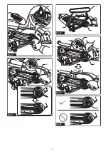
►
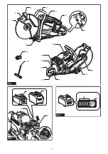
Fig.4:
1.
Overload indicator
Switch action
WARNING:
Before installing the battery car-
tridge into the tool, always check to see that the
switch trigger actuates properly and returns to
the "OFF" position when released.
WARNING:
NEVER defeat the lock-off button
by taping down or some other means.
A switch with
a negated lock-off button may result in unintentional
operation and serious personal injury.
WARNING:
NEVER use the tool if it runs when
you simply pull the switch trigger without press-
ing the lock-off button.
A switch in need of repair
may result in unintentional operation and serious
personal injury. Return tool to a Makita service center
for proper repairs BEFORE further usage.
To prevent the switch trigger from being accidentally
pulled, a lock-off button is provided. To start the tool,
depress the lock-off button and pull the switch trigger.
Release the switch trigger to stop.
►
Fig.5:
1.
Switch trigger
2.
Lock-off button
NOTICE:
Do not pull the switch trigger hard
without pressing in the lock-off button.
This can
cause switch breakage.
Lighting the lamp
CAUTION:
Do not look in the light or see the
source of light directly.
To turn on the lamp, press the lamp button. To turn off,
press the lamp button again.
►
Fig.6:
1.
Lamp button
2.
Lamp
NOTE:
The lamp will automatically be turned off if
there is no operation with the tool for one minute.
Adjusting the wheel cover
Hold the wheel cover grip and adjust the position of the
wheel cover suitable for your work.
►
Fig.7:
1.
Wheel cover grip
Active feedback sensing technology
The tool electronically detects situations where the
wheel may be at risk to be bound. In the situation, the
tool is automatically shut off to prevent further rotation
of the spindle (it does not prevent kickback).
To restart the tool, switch off the tool first, remove the cause of
sudden drop in the rotation speed, and then turn the tool on.
Electric brake
Electric brake is activated after the tool is switched off.
The brake does not work when the power supply is shut down,
such as the battery is removed accidentally, with the switch still on.
ASSEMBLY
CAUTION:
Always be sure that the tool is
switched off and the battery cartridge is removed
before carrying out any work on the tool.
Installing or removing abrasive cut-
off wheel / diamond wheel
CAUTION:
Use only the Makita wrench to
install or remove the wheel.
CAUTION:
When installing the wheel, be sure
to tighten the bolt securely.
CAUTION:
Do not press the shaft lock button
when the wheel is rotating.
To remove the wheel, press the shaft lock button and
rotate the wheel until the wheel cannot revolve. While
the shaft lock is fully locked, turn the hex bolt counter
-
clockwise using the box wrench. Then remove the hex
bolt, flange, wheel, ring, and flange in order.
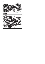
►
Fig.8:
1.
Shaft lock button
2.
Box wrench
3.
Tighten
4.
Loosen
►
Fig.9:
1.
Hex bolt
2.
Flange
3.
Ring
4.
Abrasive cut-
off wheel / diamond wheel
5.
Arrow (rotation
direction of the wheel)
To install the wheel, follow the removal procedure in reverse.
BE SURE TO TIGHTEN THE HEX BOLT SECURELY.
Summary of Contents for CE001G
Page 2: ...2 17 1 2 4 3 6 5 16 15 14 12 11 9 13 10 18 7 8 Fig 1 3 1 1 2 Fig 2 1 2 Fig 3 ...
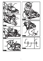
Page 3: ...3 1 Fig 4 1 2 Fig 5 2 1 Fig 6 1 Fig 7 1 2 3 4 Fig 8 3 4 2 5 2 5 1 Fig 9 2 3 4 1 2 Fig 10 ...
Page 4: ...4 1 2 3 Fig 11 1 2 3 Fig 12 1 2 3 Fig 13 Fig 14 1 Fig 15 Fig 16 1 Fig 17 ...
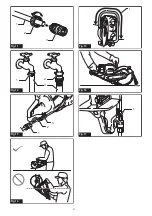
Page 5: ...5 Fig 18 1 2 Fig 19 1 1 Fig 20 1 2 3 Fig 21 ...
Page 6: ...6 1 2 Fig 22 1 2 3 Fig 23 1 2 3 Fig 24 1 2 Fig 25 1 Fig 26 ...
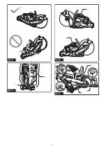
Page 7: ...7 1 Fig 27 1 2 3 Fig 28 ...
Page 106: ...106 ...
Page 107: ...107 ...


