background image

Summary of Contents for CURVED PLANER 1001

Page 1: ...Curved Planer Planing width 82 mm 13 114 82 mm 3 1 4 MODEL 1001 Planing depth No load speed Overall length Net weight 3 mm 1118 l 12 000 370 mm 1 14 1 2 1 6 0 kg 113 2 lbsl IRPMI INSTRUCTION MANUAL ...

Page 2: ...mended when working outdoors Wear protective hair covering to contain long hair USE SAFETY GLASSES Also use face or dust mask if cutting operation is dusty DON T ABUSE CORD Never carry tool by cord or yank it to disconnect from receptacle Keep cord from heat oil and sharp edges SECURE WORK Use clamps or a vise to hold work It s safer than using your hand and it frees both hands to operate tool DON...

Page 3: ... turn it on and off 19 GUARD AGAINST ELECTRIC SHOCK Prevent body contact with grounded surfaces For example pipes radiators ranges refrigerator enclosures 20 PROPER GROUNDING This tool should be grounded while in use to protect the operator from electric shock 21 EXTENSIONCORDS Use only three wire extension cords which have three prong grounding type plugs and three pole receptacles which accept t...

Page 4: ... not contacting the workpiece before the switch is turned on 9 Wait until the blade attains full speed before cutting area fore operation IO Keep at least 200 mm 8 away from the tool at all times 11 Always switch off and wait for the blades to come to a complete stop be 12 Never stick your finger into the chip chute Chute may jam when cutting 13 Do not leave the tool running Operate the tool only ...

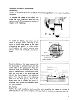
Page 5: ...lly tool break down Place the blade on the gauge base so that the blade edge is perfectly flush with the inside edge of the gauge plate Place the adjusting plate on the blade then simply press in the heel of the adjustingplateflush with the back side of the gauge base and tighten the two screws on the adjusting plate Now slip the heel of the adjusting plate into the drum groove then fit the drum c...

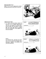
Page 6: ...e planing job raise the front base for a convex plan ing job lower the front base In either case the front base must be aligned with the cutting line Then tighten the wing nut securely NOTE As explained later although the objec tive is to cut until the cutting line is eventually reached the planing must take place gradually IConvex w I Cutting line I WlnO nut IConcave Cutting line 6 ...

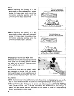
Page 7: ...ool always check to see that the trigger switch actuates properly and returns to the OFF position when released Planingoperation First rest the tool front base flat upon the workpiece surface without the blades mak ing any contact Switch on and wait until the blades attain full speed Then move the tool gently forward Apply pressureon the front of tool a t the start of planing and a t the back a t ...

Page 8: ...iplappingor corner cuts flush cuts up against a wall remove the wing bolt to take off the drum cover allowingflush sidework NOTE Corner cuts flush cuts up against a wall are impossible of course if the tool cannot be moved forward or backward because of a wall or something blocking the tool path WARNING With the drum cover removedfor corner cuts flush cuts or shiplapping be very careful not to tou...

Page 9: ...a fine edge First loosen the two wing nuts on the holder and insert the blades A and B so that they contact the sides C and D Then tighten the wing nuts Immerse the dressing stone in water for 2 or 3 minutes before sharpening Hold the holder so that the blades both contact the dressing stone for simultaneous sharpening at the same angle I 9 ...

Page 10: ...shes clean and free to slip in the holders Both carbon brushes should be replaced at the sametime Useonly Makita carbon brushes Use a screwdriver to remove the brush holder caps Take out the worn carbon brushes insert the new onesand secure the brush holder caps Limit mark To maintain product SAFETY and RELIABILITY repairs any other maintenance or adjustment should be performed by Makita Authorize...

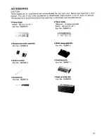
Page 11: ...ories or attachments should be used only in the proper and intended manner 0 Planer blade Width 82 mm 3 1 4 Part No 793004 6 0 Sharpening holder assembly Part No 123004 6 0 Socket wrench Part No 782209 3 0 Screwdriver Part No 783002 8 0 Planer blade Material Tungsten carbide Width 82 mm 3 1 4 Part No 793007 0 0 Blade gauge assembly Part No 123062 2 0 Dressingstone Part No 794061 7 0 Steel carrying...

Page 12: ...Jan 26 89 EN 82 mm 3 1 4 CURVED PLANER Model 1001 Note The switch noise suppressor and other part configuratlons may differ from country to country 12 ...

Page 13: ...8 80 Name Plate 33 34 35 36 3 1 38 3Y 40 41 42 43 44 45 46 4 1 48 49 50 51 52 53 54 55 56 5 1 58 59 60 61 62 63 64 65 ___ 1 1 1 1 1 1 1 3 2 1 1 1 2 1 1 4 1 1 1 1 1 1 1 1 2 4 1 1 1 1 1 1 1 Jan 2 6 8 9 EN DESCRIPTION Set Bo11M 8 Knob 50 Flaf Washer I O Noise Suppressor Swttch Pan Head Screw M4x8 IWith Washer1 Handle Cover Countersunk Head Screw M4x30 IWith Washer Pan Head Screw M4x30 With Washeri Be...

Page 14: ...14 ...

Page 15: ......

Page 16: ...Makita Corporation 3 11 8 Sumiyoshi cho Anjo Aichi 446 Japan 883000A0 PRINTED IN JAPAN I991 1 0 E ...

Reviews: