18
Cleaning the air cleaner (filter)
– Unscrew screw (1).
– Turn the choke lever (4) to the fully closed side, and keep the carburetor away
from any dust or dirt.
– Remove the air cleaner cover (3).
– Remove the sponge element (2), wash it in lukewarm water and dry it
completely.
– After cleaning, put back the air cleaner cover (3) and fasten it with screw (1).
NOTE: If there is excessive dust or dirt adhering to the air cleaner, clean it every
day. A clogged air cleaner may make it difficult or impossible to start the
engine, or may increase the engine rotational speed.
Checking the spark plug
– Only use the supplied universal wrench to remove or to install the spark plug.
– The gap between the two electrodes of the spark plug should be 0.6-0.7mm
(0.024”-0.028”). If the gap is too wide or too narrow, adjust it. If the spark plug
is clogged with carton or dirty, clean it thoroughly or replace it.
CAUTION: Never touch the spark plug connector while the engine is running
(danger of high voltage electric shock).
Supply of grease to gear case
– Supply grease (Shell Alvania 3 or equivalent) to the gear case through the
grease hole every 30 hours. (Genuine MAKITA grease may be purchased
from your MAKITA dealer.)
Suction head in the fuel tank
– The fuel filler (5) of the suction head is used to supply the fuel required by the
carburetor.
– Visually inspect the fuel filter periodically. To inspect the filter, open the tank
cap, use a wire hook and pull out the suction head through the tank opening.
Replace the filter if it has hardened, become particularly dirty, or clogged.
– Insufficient fuel supply may result in the maximum permissible speed being
exceeded. Therefore, the fuel filter must be replaced at least quarterly to
ensure satisfactory fuel supply to the carburetor.
Any other maintenance or adjustment work that is not described in this manual must only be performed by Authorized Service Agents.
0.6mm-0.7mm
(0.024”-0.028”)
Grease hole
– First, place the equipment on the ground.
– Gently press the primer pump (5) repeatedly (7-10 times) until fuel comes into
the primer pump.
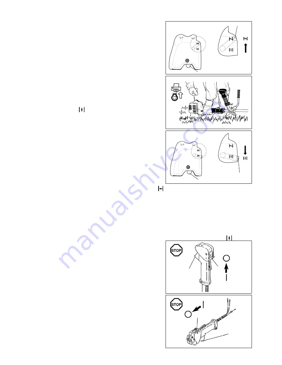
– Close the choke lever (6).
Choke opening:
• Fully closed in cold temperatures or when the engine is cold
• Fully or half open for restart while the engine is still warm
– Firmly hold the clutch case with your left hand, as illustrated.
– Slowly pull the starter grip until you feel resistance, and then continue to pull
sharply.
– Do not pull out the starter rope to its full extent, and do not allow the starter
handle to retract by itself. Maintain control of the starter rope and ensure it
retracts slowly.
– Repeat the starting operation until you hear the engine's initial ignitions.
– Depress the choke lever (6) (
) and pull the starter rope again until the
engine starts.
– As soon as the engine starts, immediately tap and release the throttle, to
release the half-throttle lock and allow the engine to idle.
– Run the engine for approximately one minute at a moderate speed before
applying full throttle.
NOTE: – If you pull the starter handle repeatedly when the choke lever is in the at “
” position, the engine will not start easily due to excessive
fuel intake.
– If excessive fuel intake occurs, remove the spark plug and pull the starter handle slowly to remove excess fuel. Also, dry the electrode
section of the spark plug.
Caution during operation:
If the throttle lever is opened fully during a no-load operation, the engine revolutions increase over 10,000 min
-1
. Never operate the engine at a
higher speed than required, and keep the revolutions at an approximate speed of 6,000 - 8,000 min
-1
.
CAUTION: Always reduce the engine revolutions when the equipment is not being used for work.
Operating the equipment at high revolutions when not being used for work will shorten the lifespan of the equipment.
Warm start
– Follow the instructions for cold start above, except without moving the choke lever (choke lever remains in the down position (
)).
Stopping
– Release the throttle lever (3) fully, and when the engine rpm has lowered,
push the I-O switch (1) to "O" position to stop the engine.
– Be aware that the cutting head may not stop immediately, and always allow it
to slow down and stop fully by itself.
(1)
(3)
(1)
(3)
DBC260U
DBC260L
(3)
(2)
(4)
(1)
(5)
(6)
(5)
CLOSE
(6)
(5)
OPEN
15
Summary of Contents for DBC260U
Page 2: ......
Page 105: ......
Page 106: ...Makita Corporation Anjo Aichi Japan www makita com 885165 932 ...


