15 ENGLISH
Connecting with vacuum cleaner
Optional accessory
When you wish to perform clean sanding operation, connect
a Makita vacuum cleaner to your tool. Use either an optional
horse 28 mm or a combination of front cuffs 22 and hose
provided with the cleaner to establish a connection.
►
Fig.21:
1.
Dust spout
2.
Front cuffs
3.
Hose
4.
Vacuum cleaner
Installing and removing battery protector
Optional accessory
The battery protector is intended for protecting the
workpiece and battery.
►
Fig.22:
1.
Battery protector
CAUTION:
Never hand hold a battery pro
-
tector when carrying the tool from one area to
another or when holding the tool while not in use.
NOTE:
The battery protector cannot be used with the
thin batteries, such as BL1815N and BL1820B.
To install the battery protector, follow the steps below.
1.
Insert the battery into the battery protector as
shown in the figure.
►
Fig.23
2.
Push the battery into the battery protector so that the
bosses in the battery protector fit the holes on the battery.
►
Fig.24:
1.
Hole
2.
Boss
3.
Make sure that the four corners are firmly hooked
with the battery protector.
►
Fig.25
To remove the battery protector, unhook the four cor
-
ners, and slowly pull out the battery from the battery
protector so that the bosses comes out of the holes on
the battery. While pulling the battery, hold the battery
and battery protector firmly.
OPERATION
Sanding operation
CAUTION:
Never run the tool without the
abrasive paper.
You may seriously damage the pad.
CAUTION:
Never force the tool.
Excessive
pressure may decrease the sanding efficiency, dam
-
age the abrasive paper and/or shorten tool life.
Sanding open areas
1.
Hold the tool firmly with your both hands, one
hand on the handle and the other on the front grip.
2.
Turn the tool on and wait until it attains full speed.
3.
Gently place the tool on the workpiece surface.
4.
Keep the entire pad level and even with the sur
-
face and apply slight pressure on the tool.
►
Fig.26
Sanding confined areas
1.
Detach the front grip from the tool.
2.
Hold the handle with one hand.
3.
Turn the tool on and wait until it attains full speed.
4.
Gently place the tool on the workpiece surface.
5.
Keep the entire pad level and even with the sur
-
face and apply slight pressure on the tool.
6.
Move the tool along curves, wall faces and in other
confined spaces, sanding with the front and corner
edges of the pad as you need.
►
Fig.27
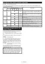
WIRELESS ACTIVATION
FUNCTION
For model DBO381 only
NOTICE:
The wireless function is only available
when the supported vacuum cleaner is being
installed.
What you can do with the wireless
activation function
The wireless activation function enables clean and com-
fortable operation. By connecting a supported vacuum
cleaner to the tool, you can run the vacuum cleaner
automatically along with the switch operation of the tool.
►
Fig.28
To use the wireless activation function, prepare following items:
•
A wireless unit (optional accessory)
•
A vacuum cleaner which supports the wireless
activation function
The overview of the wireless activation function setting is
as follows. Refer to each section for detail procedures.
1.
Installing the wireless unit
2.
Tool registration for the vacuum cleaner
3.
Starting the wireless activation function
Installing the wireless unit
Optional accessory
CAUTION:
Place the tool on a flat and stable
surface when installing the wireless unit.
NOTICE:
Clean the dust and dirt on the tool before
installing the wireless unit.
Dust or dirt may cause
malfunction if it comes into the slot of the wireless unit.
NOTICE:
To prevent the malfunction caused by static,
touch a static discharging material, such as a metal part
of the tool, before picking up the wireless unit.
NOTICE:
When installing the wireless unit, always
be sure that the wireless unit is inserted in the cor-
rect direction and the lid is completely closed.
Summary of Contents for DBO380
Page 2: ...2 1 2 3 Fig 1 1 2 Fig 2 1 2 3 Fig 3 1 Fig 4 1 2 3 5 4 1 4 5 2 3 Fig 5 1 2 3 Fig 6 ...
Page 5: ...5 1 2 3 3 Fig 19 1 2 3 4 Fig 20 1 2 3 4 Fig 21 1 Fig 22 Fig 23 2 1 Fig 24 ...
Page 6: ...6 Fig 25 Fig 26 Fig 27 Fig 28 1 Fig 29 1 2 3 4 Fig 30 ...
Page 7: ...7 1 2 3 Fig 31 1 Fig 32 1 2 1 2 Fig 33 Fig 34 1 Fig 35 ...
Page 8: ...8 1 2 Fig 36 1 Fig 37 1 Fig 38 1 2 1 2 Fig 39 ...
Page 127: ...127 ...


