background image

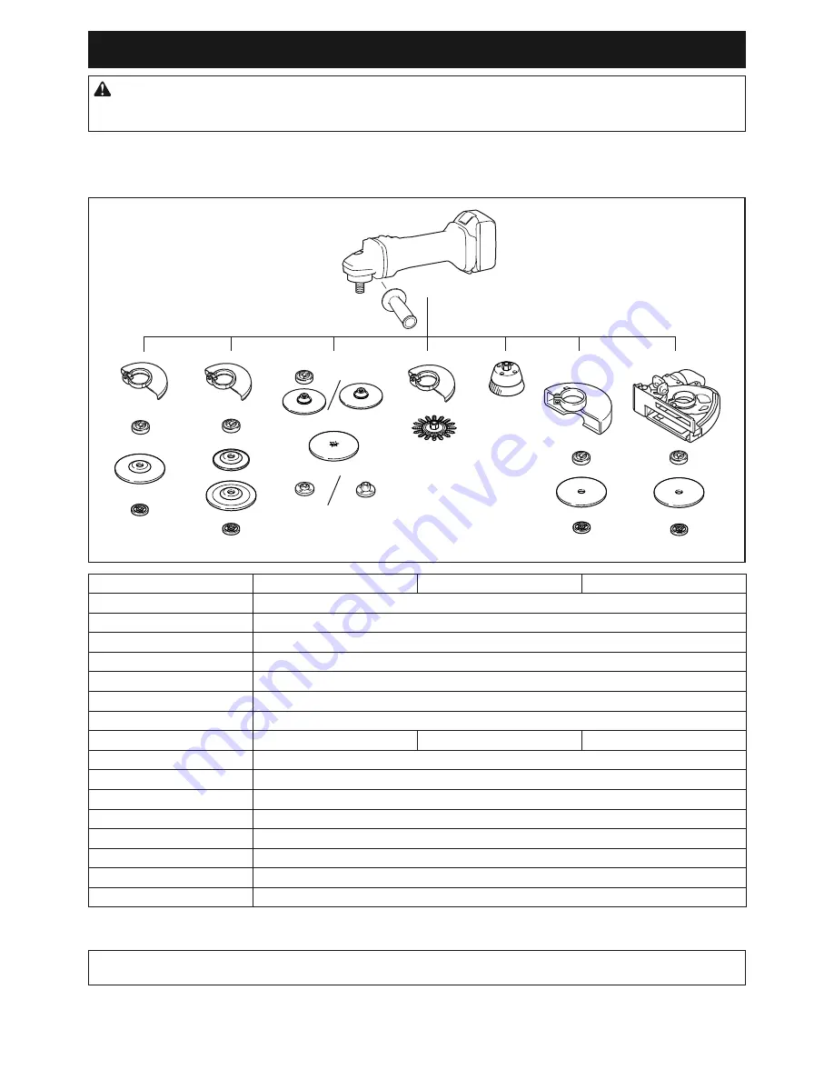
OPTIONAL ACCESSORIES

CAUTION:


These accessories or attachments are recommended for use with your Makita tool spec-

iied in this manual.

 The use of any other accessories or attachments might present a risk of injury to persons. 

Only use accessory or attachment for its stated purpose.

If you need any assistance for more details regarding these accessories, ask your local Makita Service Center.
• 

Makita genuine battery and charger

• 

Wireless unit (For models with wireless activation function)

1

2

5

2

2

11

12

4

3

5

6

7

8

9

10

13

15

3

14

5

3

14

5

3

-

100 mm (4″) model

115 mm (4-1/2″) model

125 mm (5″) model

1

Grip 36

2

Wheel Guard (for grinding wheel)

3

Inner lange

4

Depressed center wheel / Flap disc

5

Lock nut

6

Back up pad

7

Flex wheel

8

Inner lange and rubber pad 76

Rubber pad 100

Rubber pad 115

9

Abrasive disc

10

Sanding lock nut

11

Wire wheel brush

12

Wire cup brush

13

Wheel Guard (for cut-off wheel) *1

14

Abrasive cut-off wheel / Diamond wheel

15

Dust collecting wheel guard

-

Lock nut wrench

NOTE:

 *1 In some European countries, when using a diamond wheel, the ordinary guard can be used instead of the 

special guard covering the both side of the wheel. Follow the regulations in your country.

NOTE:

 Some items in the list may be included in the tool package as standard accessories. They may differ from 

country to country.

25

ENGLISH

Summary of Contents for DGA418

Page 1: ...INSTRUCTION MANUAL Cordless Angle Grinder DGA417 DGA418 DGA467 DGA468 DGA517 DGA518 ENGLISH Original instructions Read before use ...

Page 2: ...eight 2 4 3 1 kg Electric brake Wireless activation function Due to our continuing program of research and development the speciications herein are subject to change without notice Speciications may differ from country to country The weight may differ depending on the attachment s including the battery cartridge The lightest and heavi est combination according to EPTA Procedure 01 2014 are shown i...

Page 3: ...terials without the use of water Noise The typical A weighted noise level determined according to EN60745 Model Sound pressure level LpA dB A Sound power level LWA dB A Uncertainty K dB A DGA417 80 3 DGA418 80 3 DGA467 80 3 DGA468 80 3 DGA517 79 3 DGA518 79 3 The noise level under working may exceed 80 dB A WARNING Wear ear protection Vibration The vibration total value tri axial vector sum determ...

Page 4: ...on of Conformity For European countries only The EC declaration of conformity is included as Annex A to this instruction manual SAFETY WARNINGS General power tool safety warnings WARNING Read all safety warnings instruc tions illustrations and speciications provided with this power tool Failure to follow all instructions listed below may result in electric shock ire and or serious injury Save all ...

Page 5: ...ry within a fraction of a second 9 Always wear protective goggles to protect your eyes from injury when using power tools The goggles must comply with ANSI Z87 1 in the USA EN 166 in Europe or AS NZS 1336 in Australia New Zealand In Australia New Zealand it is legally required to wear a face shield to protect your face too It is an employer s responsibility to enforce the use of appropriate safety...

Page 6: ...s not assure safe operation 4 The rated speed of the accessory must be at least equal to the maximum speed marked on the power tool Accessories running faster than their rated speed can break and ly apart 5 The outside diameter and the thickness of your accessory must be within the capacity rating of your power tool Incorrectly sized accessories cannot be adequately guarded or controlled 6 Threade...

Page 7: ...d to the power tool and positioned for maximum safety so the least amount of wheel is exposed towards the operator The guard helps to protect the operator from broken wheel fragments acci dental contact with wheel and sparks that could ignite clothing 4 Wheels must be used only for recommended applications For example do not grind with the side of cut off wheel Abrasive cut off wheels are intended...

Page 8: ...tool on any materials contain ing asbestos 17 When use cut off wheel always work with the dust collecting wheel guard required by domestic regulation 18 Cutting discs must not be subjected to any lateral pressure 19 Do not use cloth work gloves during operation Fibers from cloth gloves may enter the tool which causes tool breakage SAVE THESE INSTRUCTIONS WARNING DO NOT let comfort or familiarity w...

Page 9: ...they are not harmful to the user 9 The wireless unit is an accurate instrument Be careful not to drop or strike the wireless unit 10 Avoid touching the terminal of the wireless unit with bare hands or metallic materials 11 Always remove the battery on the tool when installing the wireless unit 12 When opening the lid of the slot avoid the place where dust and water may come into the slot Always ke...

Page 10: ...ousing and slip it into place Insert it all the way until it locks in place with a little click If you can see the red indicator on the upper side of the button it is not locked completely CAUTION Always install the battery cartridge fully until the red indicator cannot be seen If not it may accidentally fall out of the tool causing injury to you or someone around you CAUTION Do not install the ba...

Page 11: ...become overloaded Then turn the tool on to restart Overheat protection When the tool is overheated the tool stops automati cally and the battery indicator shows following state In this situation let the tool cool before turning the tool on again On Blinking If the tool does not start the battery may be overheated In this situation let the battery cool before starting the tool again Overdischarge p...

Page 12: ... rotation speed 1 1 Speed adjusting dial Number Speed 1 3 000 min 1 2 4 500 min 1 3 6 000 min 1 4 7 500 min 1 5 8 500 min 1 NOTICE If the tool is operated continuously at low speed for a long time the motor will get over loaded resulting in tool malfunction NOTICE When changing the speed dial from 5 to 1 turn the dial counterclockwise Do not turn the dial clockwise forcibly Automatic speed change ...

Page 13: ...nd wheel be sure to use only the special wheel guard designed for use with cut off wheels In some European countries when using a diamond wheel the ordinary guard can be used Follow the regulations in your country For tool with locking screw type wheel guard Mount the wheel guard with the protrusions on the wheel guard band aligned with the notches on the bear ing box Then rotate the wheel guard t...

Page 14: ...the straight part at the bottom of the spindle Fit the depressed center wheel lap disc on the inner lange and screw the lock nut onto the spindle 1 2 4 3 1 Lock nut 2 Depressed center wheel 3 Inner lange 4 Mounting part To tighten the lock nut press the shaft lock irmly so that the spindle cannot revolve then use the lock nut wrench and securely tighten clockwise 1 2 1 Lock nut wrench 2 Shaft lock...

Page 15: ...hat they ignite dust and the ilter inside the vacuum cleaner To avoid dusty environment caused by masonry cutting use a dust collecting wheel guard and a vacuum cleaner Refer to the instruction manual attached to the dust collecting wheel guard for assembling and using it 2 1 1 Dust collecting wheel guard 2 Hose of the vac uum cleaner OPERATION WARNING It should never be necessary to force the too...

Page 16: ...breakage and overheating of the motor may occur WARNING Do not start the cutting operation in the workpiece Let the wheel reach full speed and carefully enter into the cut moving the tool forward over the workpiece surface The wheel may bind walk up or kickback if the power tool is started in the workpiece WARNING During cutting operations never change the angle of the wheel Placing side pres sure...

Page 17: ...pindle and tighten with supplied wrench NOTICE Avoid applying too much pressure which causes over bending of wires when using brush It may lead to premature breakage Operation with wire wheel brush Optional accessory CAUTION Check operation of wire wheel brush by running tool with no load insuring that no one is in front of or in line with the wire wheel brush CAUTION Do not use wire wheel brush t...

Page 18: ...N Place the tool on a lat and stable surface when installing the wireless unit NOTICE Clean the dust and dirt on the tool before installing the wireless unit Dust or dirt may cause malfunction if it comes into the slot of the wireless unit NOTICE To prevent the malfunction caused by static touch a static discharging material such as a metal part of the tool before picking up the wireless unit NOTI...

Page 19: ...witch trigger or turn on the power switch on the vacuum cleaner NOTE Refer to the instruction manual of the vacuum cleaner too If you wish to activate the vacuum cleaner along with the switch operation of the tool inish the tool registra tion beforehand 1 Install the batteries to the vacuum cleaner and the tool 2 Set the stand by switch on the vacuum cleaner to AUTO 1 1 Stand by switch 3 Press the...

Page 20: ... cleaner to AUTO 1 1 Stand by switch 4 Push the wireless activation button on the tool briely The wireless activation lamp will blink in blue 1 2 1 Wireless activation button 2 Wireless activation lamp 5 Pull the switch trigger of the tool Check if the vacuum cleaner runs while the switch trigger is being pulled To stop the wireless activation of the vacuum cleaner push the wireless activation but...

Page 21: ...cuum cleaner is available and the tool is running Tool registration Green 20 seconds Ready for the tool registration Waiting for the registration by the vacuum cleaner 2 seconds The tool registration has been inished The wireless activation lamp will start blinking in blue Cancelling tool registration Red 20 seconds Ready for the cancellation of the tool registration Waiting for the cancellation b...

Page 22: ...and then become red After that press the wireless activation button on the tool in the same way 1 2 1 2 1 Wireless activation button 2 Wireless activation lamp If the cancellation is performed successfully the wire less activation lamps will light up in red for 2 seconds and start blinking in blue NOTE The wireless activation lamps inish blinking in red after 20 seconds elapsed Press the wireless ...

Page 23: ...led into the tool Install the wireless unit correctly The terminal of the wireless unit and or the slot is dirty Gently wipe off dust and dirt on the terminal of the wireless unit and clean the slot The stand by switch on the vacuum cleaner is not set to AUTO Set the stand by switch on the vacuum cleaner to AUTO No power supply Supply the power to the tool and the vacuum cleaner Incorrect operatio...

Page 24: ... out of the transmission range Get the tool and vacuum cleaner closer each other The maximum transmission distance is approxi mately 10 m however it may vary according to the circumstances Radio disturbance by other appliances which generate high intensity radio waves Keep the tool and vacuum cleaner away from the appliances such as Wi Fi devices and microwave ovens The vacuum cleaner runs while t...

Page 25: ...15 mm 4 1 2 model 125 mm 5 model 1 Grip 36 2 Wheel Guard for grinding wheel 3 Inner lange 4 Depressed center wheel Flap disc 5 Lock nut 6 Back up pad 7 Flex wheel 8 Inner lange and rubber pad 76 Rubber pad 100 Rubber pad 115 9 Abrasive disc 10 Sanding lock nut 11 Wire wheel brush 12 Wire cup brush 13 Wheel Guard for cut off wheel 1 14 Abrasive cut off wheel Diamond wheel 15 Dust collecting wheel g...

Page 26: ...26 ...

Page 27: ...27 ...

Page 28: ...www makita com Makita Europe N V Makita Corporation 3 11 8 Sumiyoshi cho Anjo Aichi 446 8502 Japan Jan Baptist Vinkstraat 2 3070 Kortenberg Belgium 885616 226 EN 20170623 ...

Reviews: