
6
ENGLISH
Battery tool use and care
1.
Recharge only with the charger speciied by
the manufacturer.
A charger that is suitable for
one type of battery pack may create a risk of ire
when used with another battery pack.
2.
Use power tools only with speciically desig
-
nated battery packs.
Use of any other battery
packs may create a risk of injury and ire.
3.
When battery pack is not in use, keep it away
from other metal objects, like paper clips,
coins, keys, nails, screws or other small metal
objects, that can make a connection from one
terminal to another.
Shorting the battery termi
-
nals together may cause burns or a ire.
4.
Under abusive conditions, liquid may be
ejected from the battery; avoid contact. If con-
tact accidentally occurs, lush with water. If
liquid contacts eyes, additionally seek medical
help.
Liquid ejected from the battery may cause
irritation or burns.
5.
Do not use a battery pack or tool that is dam-
aged or modiied.
Damaged or modiied batteries
may exhibit unpredictable behaviour resulting in
ire, explosion or risk of injury.
6.
Do not expose a battery pack or tool to ire or
excessive temperature.
Exposure to ire or tem
-
perature above 130 °C may cause explosion.
7.
Follow all charging instructions and do not
charge the battery pack or tool outside the
temperature range speciied in the instruc
-
tions.
Charging improperly or at temperatures
outside the speciied range may damage the
battery and increase the risk of ire.
Service
1.
Have your power tool serviced by a qualiied
repair person using only identical replacement
parts.
This will ensure that the safety of the power
tool is maintained.
2.
Never service damaged battery packs.
Service
of battery packs should only be performed by the
manufacturer or authorized service providers.
3.
Follow instruction for lubricating and chang-
ing accessories.
Cordless grinder safety warnings
Safety Warnings Common for Grinding, Sanding,
Wire Brushing, or Abrasive Cutting-Off Operations:
1.
This power tool is intended to function as a
grinder, sander, wire brush or cut-off tool.
Read all safety warnings, instructions, illus-
trations and speciications provided with this
power tool.
Failure to follow all instructions listed
below may result in electric shock, ire and/or
serious injury.
2.
Operations such as polishing are not rec-
ommended to be performed with this power
tool.
Operations for which the power tool was not
designed may create a hazard and cause per
-
sonal injury.
3.
Do not use accessories which are not specii
-
cally designed and recommended by the tool
manufacturer.
Just because the accessory can
be attached to your power tool, it does not assure
safe operation.
4.
The rated speed of the accessory must be at
least equal to the maximum speed marked on
the power tool.
Accessories running faster than
their rated speed can break and ly apart.
5.
The outside diameter and the thickness of your
accessory must be within the capacity rating
of your power tool.
Incorrectly sized accessories
cannot be adequately guarded or controlled.
6.
Threaded mounting of accessories must
match the grinder spindle thread. For acces-
sories mounted by langes, the arbour hole of
the accessory must it the locating diameter
of the lange.
Accessories that do not match the
mounting hardware of the power tool will run out of
balance, vibrate excessively and may cause loss
of control.
7.
Do not use a damaged accessory. Before each
use inspect the accessory such as abrasive
wheels for chips and cracks, backing pad for
cracks, tear or excess wear, wire brush for
loose or cracked wires. If power tool or acces-
sory is dropped, inspect for damage or install
an undamaged accessory. After inspecting and
installing an accessory, position yourself and
bystanders away from the plane of the rotating
accessory and run the power tool at maximum
no-load speed for one minute.
Damaged acces-
sories will normally break apart during this test
time.
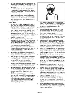
8.
Wear personal protective equipment.
Depending on application, use face shield,
safety goggles or safety glasses. As appro-
priate, wear dust mask, hearing protectors,
gloves and workshop apron capable of stop-
ping small abrasive or workpiece fragments.
The eye protection must be capable of stopping
lying debris generated by various operations.
The dust mask or respirator must be capable of
iltrating particles generated by your operation.
Prolonged exposure to high intensity noise may
cause hearing loss.
9.
Keep bystanders a safe distance away from
work area. Anyone entering the work area
must wear personal protective equipment.
Fragments of workpiece or of a broken accessory
may ly away and cause injury beyond immediate
area of operation.
10.
Hold the power tool by insulated gripping
surfaces only, when performing an operation
where the cutting tool may contact hidden
wiring.
Contact with a "live" wire will also make
exposed metal parts of the power tool "live" and
could give the operator an electric shock.
11.
Never lay the power tool down until the acces-
sory has come to a complete stop.
The spinning
accessory may grab the surface and pull the
power tool out of your control.
12.
Do not run the power tool while carrying it at
your side.
Accidental contact with the spinning
accessory could snag your clothing, pulling the
accessory into your body.
13.
Regularly clean the power tool’s air vents.
The
motor’s fan will draw the dust inside the housing
and excessive accumulation of powdered metal
may cause electrical hazards.