background image

10 ENGLISH

14. 

Do not press the wireless activation button 

on the wireless unit too hard and/or press the 

button with an object with a sharp edge.

15. 

Always close the lid of the slot when 

operating.

16. 

Do not remove the wireless unit from the slot 

while the power is being supplied to the tool.


Doing so may cause a malfunction of the wireless 

unit.

17. 

Do not remove the sticker on the wireless unit.

18. 

Do not put any sticker on the wireless unit.

19. 

Do not leave the wireless unit in a place where 

static electricity or electrical noise could be 

generated.

20. 

Do not leave the wireless unit in a place sub-

ject to high heat, such as a car sitting in the 

sun.

21. 

Do not leave the wireless unit in a dusty or 

powdery place or in a place corrosive gas 

could be generated.

22. 

Sudden change of the temperature may bedew 

the wireless unit. Do not use the wireless unit 

until the dew is completely dried. 

23. 

When cleaning the wireless unit, gently wipe 

with a dry soft cloth. Do not use benzine, thin-

ner, conductive grease or the like.

24. 

When storing the wireless unit, keep it in the 

supplied case or a static-free container.

25. 

Do not insert any devices other than Makita 

wireless unit into the slot on the tool.

26. 

Do not use the tool with the lid of the slot dam-

aged.

 Water, dust, and dirt come into the slot may 

cause malfunction.

27. 

Do not pull and/or twist the lid of the slot more 

than necessary.

 Restore the lid if it comes off 

from the tool.

28. 

Replace the lid of the slot if it is lost or 

damaged.

SAVE THESE INSTRUCTIONS.

FUNCTIONAL 

DESCRIPTION

CAUTION:


Always be sure that the tool is 

switched off and the battery cartridge is removed 

before adjusting or checking function on the tool.

Installing or removing battery 

cartridge

CAUTION:


Always switch off the tool before 

installing or removing of the battery cartridge.

CAUTION:


Hold the tool and the battery car-

tridge firmly when installing or removing battery 

cartridge.

 Failure to hold the tool and the battery 

cartridge firmly may cause them to slip off your hands 

and result in damage to the tool and battery cartridge 

and a personal injury.

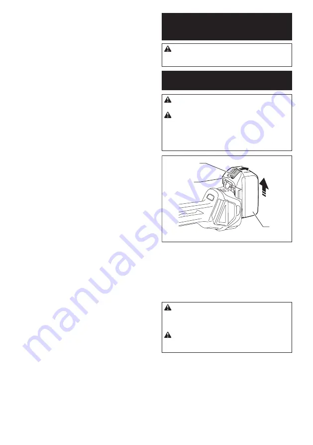
2

1

3

►    

1.

 Red indicator 

2.

 Button 

3.

 Battery cartridge

To remove the battery cartridge, slide it from the tool 

while sliding the button on the front of the cartridge.

To install the battery cartridge, align the tongue on the 

battery cartridge with the groove in the housing and slip 

it into place. Insert it all the way until it locks in place 

with a little click. If you can see the red indicator on the 

upper side of the button, it is not locked completely.

CAUTION:


Always install the battery cartridge 

fully until the red indicator cannot be seen.

 If not, 

it may accidentally fall out of the tool, causing injury to 

you or someone around you.

CAUTION:


Do not install the battery cartridge 

forcibly.

 If the cartridge does not slide in easily, it is 

not being inserted correctly.

Summary of Contents for DGA461

Page 1: ...INSTRUCTION MANUAL Cordless Angle Grinder DGA411 DGA412 DGA413 DGA414 DGA461 DGA462 DGA463 DGA464 DGA511 DGA512 DGA513 DGA514 ENGLISH Original instructions Read before use ...

Page 2: ...8 country specific Rated speed n 8 500 min 1 Overall length 382 mm Rated voltage D C 18 V Net weight 2 3 3 0 kg 2 4 3 0 kg Electric brake Wireless activation function Due to our continuing program of research and development the specifications herein are subject to change without notice Specifications may differ from country to country The weight may differ depending on the attachment s including ...

Page 3: ...ing facility Intended use The tool is intended for grinding sanding and cutting of metal and stone materials without the use of water Noise The typical A weighted noise level determined according to EN60745 Model Sound pressure level LpA dB A Sound power level LWA dB A Uncertainty K dB A DGA411 80 3 DGA412 80 3 DGA413 80 3 DGA414 80 3 DGA461 79 3 DGA462 79 3 DGA463 79 3 DGA464 79 3 DGA511 79 3 DGA...

Page 4: ...ess 1 5 DGA511 2 5 m s2 or less 1 5 DGA512 2 5 m s2 or less 1 5 DGA513 2 5 m s2 or less 1 5 DGA514 2 5 m s2 or less 1 5 Work mode disc sanding with anti vibration side grip Model Vibration emission ah DS m s 2 Uncertainty K m s 2 DGA411 2 5 m s2 or less 1 5 DGA412 2 5 m s2 or less 1 5 DGA413 2 5 m s2 or less 1 5 DGA414 2 5 m s2 or less 1 5 DGA461 2 5 m s2 or less 1 5 DGA462 2 5 m s2 or less 1 5 DG...

Page 5: ... the cord for carrying pulling or unplugging the power tool Keep cord away from heat oil sharp edges or moving parts Damaged or entangled cords increase the risk of electric shock 5 When operating a power tool outdoors use an extension cord suitable for outdoor use Use of a cord suitable for outdoor use reduces the risk of electric shock 6 If operating a power tool in a damp location is unavoidabl...

Page 6: ...ntangle ment of cloth work gloves in the moving parts may result in personal injury Battery tool use and care 1 Recharge only with the charger specified by the manufacturer A charger that is suitable for one type of battery pack may create a risk of fire when used with another battery pack 2 Use power tools only with specifically desig nated battery packs Use of any other battery packs may create ...

Page 7: ...n the power tool s air vents The motor s fan will draw the dust inside the housing and excessive accumulation of powdered metal may cause electrical hazards 14 Do not operate the power tool near flammable materials Sparks could ignite these materials 15 Do not use accessories that require liquid coolants Using water or other liquid coolants may result in electrocution or shock Kickback and Related...

Page 8: ...nding disc paper Follow manufacturers recommen dations when selecting sanding paper Larger sanding paper extending beyond the sanding pad presents a laceration hazard and may cause snagging tearing of the disc or kickback Safety Warnings Specific for Wire Brushing Operations 1 Be aware that wire bristles are thrown by the brush even during ordinary operation Do not overstress the wires by applying...

Page 9: ...move around in the packaging 11 Follow your local regulations relating to dis posal of battery 12 Use the batteries only with the products specified by Makita Installing the batteries to non compliant products may result in a fire exces sive heat explosion or leak of electrolyte SAVE THESE INSTRUCTIONS CAUTION Only use genuine Makita batteries Use of non genuine Makita batteries or batteries that ...

Page 10: ...ot pull and or twist the lid of the slot more than necessary Restore the lid if it comes off from the tool 28 Replace the lid of the slot if it is lost or damaged SAVE THESE INSTRUCTIONS FUNCTIONAL DESCRIPTION CAUTION Always be sure that the tool is switched off and the battery cartridge is removed before adjusting or checking function on the tool Installing or removing battery cartridge CAUTION A...

Page 11: ...ery indicator shows the remaining battery capacity 1 1 Battery indicator The remaining battery capacity is shown as the follow ing table Battery indicator status Remaining battery capacity On Off Blinking 50 to 100 20 to 50 0 to 20 Charge the battery Tool battery protection system The tool is equipped with a tool battery protection sys tem This system automatically cuts off power to the motor to e...

Page 12: ...tion when installing or removing accessories 1 1 Shaft lock NOTICE Never actuate the shaft lock when the spindle is moving The tool may be damaged Switch action CAUTION Before installing the battery car tridge into the tool always check to see that the slide switch actuates properly and returns to the OFF position when the rear of the slide switch is depressed CAUTION Switch can be locked in ON po...

Page 13: ... the tool first remove the cause of sudden drop in the rotation speed and then turn the tool on Soft start feature Soft start feature reduces starting reaction Electric brake For model DGA413 DGA414 DGA463 DGA464 DGA513 DGA514 only Electric brake is activated after the tool is switched off The brake does not work when the power supply is shut down such as the battery is removed accidentally with t...

Page 14: ...crew securely The setting angle of the wheel guard can be adjusted with the lever 1 2 1 Screw 2 Lever To remove wheel guard follow the installation proce dure in reverse Installing or removing depressed center wheel or flap disc Optional accessory WARNING When using a depressed center wheel or flap disc the wheel guard must be fitted on the tool so that the closed side of the guard always points t...

Page 15: ...hased separately For 100 mm 4 model 1 2 3 4 1 Sanding lock nut 2 Abrasive disc 3 Rubber pad 4 Inner flange 1 Mount the inner flange onto the spindle 2 Mount the rubber pad onto the spindle 3 Fit the disc on the rubber pad and screw the sand ing lock nut onto the spindle 4 Hold the spindle with the shaft lock and securely tighten the sanding lock nut clockwise with the lock nut wrench To remove the...

Page 16: ...nd on housing and the other on the side grip handle Grinding and sanding operation 15 Turn the tool on and then apply the wheel or disc to the workpiece In general keep the edge of the wheel or disc at an angle of about 15 to the workpiece surface During the break in period with a new wheel do not work the grinder in forward direction or it may cut into the workpiece Once the edge of the wheel has...

Page 17: ... 4 4 2 3 1 Lock nut 2 Diamond wheel Thinner than 4mm 5 32 3 Diamond wheel 4mm 5 32 or thicker 4 Inner flange For 115 mm 4 1 2 125 mm 5 model When installing the abrasive cut off wheel 1 1 4 4 2 3 1 Lock nut 2 Abrasive cut off wheel Thinner than 4mm 5 32 3 Abrasive cut off wheel 4mm 5 32 or thicker 4 Inner flange When installing the diamond wheel 1 1 4 4 2 3 1 Lock nut 2 Diamond wheel Thinner than ...

Page 18: ... bending of wires when using wire wheel brush It may lead to premature breakage WIRELESS ACTIVATION FUNCTION For DGA412 DGA414 DGA462 DGA464 DGA512 DGA514 only What you can do with the wireless activation function The wireless activation function enables clean and com fortable operation By connecting a supported vacuum cleaner to the tool you can run the vacuum cleaner automatically along with the...

Page 19: ... lid when removing the wireless unit If the hooks do not catch the wireless unit close the lid completely and open it slowly again Tool registration for the vacuum cleaner NOTE A Makita vacuum cleaner supporting the wireless activation function is required for the tool registration NOTE Finish installing the wireless unit to the tool before starting the tool registration NOTE During the tool regis...

Page 20: ...e wireless acti vation lamp on the cleaner is blinking If the wireless activation lamp does not blink in green push the wire less activation button briefly and hold it down again NOTE When performing two or more tool registra tions for one vacuum cleaner finish the tool registra tion one by one Starting the wireless activation function NOTE Finish the tool registration for the vacuum cleaner prior...

Page 21: ...stop blinking in blue when there is no operation for 2 hours In this case set the stand by switch on the vacuum cleaner to AUTO and push the wireless activation button on the tool again NOTE The vacuum cleaner starts stops with a delay There is a time lag when the vacuum cleaner detects a switch operation of the tool NOTE The transmission distance of the wireless unit may vary depending on the loc...

Page 22: ...uum cleaner is available and the tool is running Tool registration Green 20 seconds Ready for the tool registration Waiting for the registration by the vacuum cleaner 2 seconds The tool registration has been finished The wireless activation lamp will start blinking in blue Cancelling tool registration Red 20 seconds Ready for the cancellation of the tool registration Waiting for the cancellation b...

Page 23: ...nd then become red After that press the wireless activation button on the tool in the same way 1 2 1 2 1 Wireless activation button 2 Wireless activation lamp If the cancellation is performed successfully the wire less activation lamps will light up in red for 2 seconds and start blinking in blue NOTE The wireless activation lamps finish blinking in red after 20 seconds elapsed Press the wireless ...

Page 24: ...led into the tool Install the wireless unit correctly The terminal of the wireless unit and or the slot is dirty Gently wipe off dust and dirt on the terminal of the wireless unit and clean the slot The stand by switch on the vacuum cleaner is not set to AUTO Set the stand by switch on the vacuum cleaner to AUTO No power supply Supply the power to the tool and the vacuum cleaner Incorrect operatio...

Page 25: ...r out of the transmission range Get the tool and vacuum cleaner closer each other The maximum transmission distance is approxi mately 10 m however it may vary according to the circumstances Radio disturbance by other appliances which generate high intensity radio waves Keep the tool and vacuum cleaner away from the appliances such as Wi Fi devices and microwave ovens The vacuum cleaner runs while ...

Page 26: ... 115 mm 4 1 2 model 125 mm 5 model 1 Grip 36 2 Wheel Guard for grinding wheel 3 Inner flange 4 Depressed center wheel Flap disc 5 Lock nut 6 Back up pad 7 Flex wheel 8 Inner flange and rubber pad 76 Rubber pad 100 Rubber pad 115 9 Abrasive disc 10 Sanding lock nut 11 Wire wheel brush 12 Wire cup brush 13 Wheel Guard for cut off wheel 1 14 Abrasive cut off wheel Diamond wheel 15 Dust collecting whe...

Page 27: ...27 ...

Page 28: ...www makita com Makita Europe N V Makita Corporation 3 11 8 Sumiyoshi cho Anjo Aichi 446 8502 Japan Jan Baptist Vinkstraat 2 3070 Kortenberg Belgium 885615 228 EN 20170626 ...

Reviews: