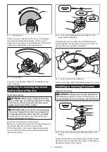
background image

11 ENGLISH

1

►    

1.

 Wheel guard

Close the lever in direction of the arrow. Then tighten 

the wheel guard with fastening the nut. Be sure to 

tighten the nut securely. The setting angle of the wheel 

guard can be adjusted by opening the lever.

1

2

►    

1.

 Lever 

2.

 Nut

To remove wheel guard, follow the installation proce

-

dure in reverse.

Installing or removing depressed 

center wheel or flap disc

Optional accessory

WARNING:


When using a depressed center 

wheel or flap disc, the wheel guard must be fitted 

on the tool so that the closed side of the guard 

always points toward the operator.

CAUTION:


Make sure that the mounting part 

of the inner flange fits into the inner diameter of 

the depressed center wheel / flap disc perfectly.


Mounting the inner flange on the wrong side may 

result in the dangerous vibration.

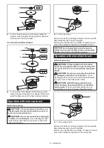
Mount the inner flange onto the spindle.

Make sure to fit the dented part of the inner flange onto 

the straight part at the bottom of the spindle.

Fit the wheel/ disc on the inner flange and screw the 

lock nut with its protrusion facing downward (facing 

towards the wheel).

1

4

2

3

►    

1.

 Lock nut 

2.

 Depressed center wheel 

3.

 Inner 

flange 

4.

 Mounting part

To tighten the lock nut, press the shaft lock firmly so 

that the spindle cannot revolve, then use the lock nut 

wrench and securely tighten clockwise.

1

2

►    

1.

 Lock nut wrench 

2.

 Shaft lock

To remove the wheel, follow the installation procedure in reverse.

Installing or removing flex wheel

Optional accessory

WARNING:


Always use supplied guard when 

flex wheel is on tool.

 Wheel can shatter during use 

and guard helps to reduce chances of personal injury.

1

4

2

3

►    

1.

 Lock nut 

2.

 Flex wheel 

3.

 Back up pad 

4.

 Inner 

flange

Follow instructions for depressed center wheel but also 

use back up pad over wheel. See order of assembly on 

accessories page in this manual.

Summary of Contents for DGA900Z

Page 1: ...INSTRUCTION MANUAL Cordless Angle Grinder DGA700 DGA900 ENGLISH Original instructions Read before use ...

Page 2: ...rinding sanding and cutting of metal and stone materials without the use of water Noise The typical A weighted noise level determined accord ing to EN60745 Model DGA700 Sound pressure level LpA 88 dB A Sound power level LWA 99 dB A Uncertainty K 3 dB A Model DGA900 Sound pressure level LpA 88 dB A Sound power level LWA 99 dB A Uncertainty K 3 dB A WARNING Wear ear protection Vibration The vibratio...

Page 3: ...ncrease the risk of electric shock 5 When operating a power tool outdoors use an extension cord suitable for outdoor use Use of a cord suitable for outdoor use reduces the risk of electric shock 6 If operating a power tool in a damp location is unavoidable use a residual current device RCD protected supply Use of an RCD reduces the risk of electric shock 7 Power tools can produce electromagnetic f...

Page 4: ... When battery pack is not in use keep it away from other metal objects like paper clips coins keys nails screws or other small metal objects that can make a connection from one terminal to another Shorting the battery termi nals together may cause burns or a fire 4 Under abusive conditions liquid may be ejected from the battery avoid contact If contact acci dentally occurs flush with water If liqu...

Page 5: ...uses the uncon trolled power tool to be forced in the direction opposite of the accessory s rotation at the point of the binding For example if an abrasive wheel is snagged or pinched by the workpiece the edge of the wheel that is entering into the pinch point can dig into the surface of the material causing the wheel to climb out or kick out The wheel may either jump toward or away from the opera...

Page 6: ...Safety Warnings 1 When using depressed centre grinding wheels be sure to use only fiberglass reinforced wheels 2 NEVER USE Stone Cup type wheels with this grinder This grinder is not designed for these types of wheels and the use of such a product may result in serious personal injury 3 Be careful not to damage the spindle the flange especially the installing surface or the lock nut Damage to thes...

Page 7: ...a tool and charger Tips for maintaining maximum battery life 1 Charge the battery cartridge before completely discharged Always stop tool operation and charge the battery cartridge when you notice less tool power 2 Never recharge a fully charged battery car tridge Overcharging shortens the battery service life 3 Charge the battery cartridge with room tem perature at 10 C 40 C 50 F 104 F Let a hot ...

Page 8: ...ry life The tool will auto matically stop during operation if the tool or battery is placed under one of the following conditions 1 1 Battery indicator Overload protection When the tool is operated in a manner that causes it to draw an abnormally high current the tool automatically stops without any indication In this situation turn the tool off and stop the application that caused the tool to bec...

Page 9: ...ase the switch lever 1 2 1 Lock off lever 2 Switch lever Automatic speed change function 1 1 Mode indicator Mode indicator status Operation mode On Off High speed mode High torque mode This tool has high speed mode and high torque mode It automatically changes operation mode depending on the work load When mode indicator lights up during operation the tool is in high torque mode Accidental re star...

Page 10: ...y the special wheel guard designed for use with cut off wheels In some European countries when using a diamond wheel the ordinary guard can be used Follow the regulations in your country For tool with locking screw type wheel guard Mount the wheel guard with the protrusions on the wheel guard band aligned with the notches on the bear ing box Then rotate the wheel guard to such an angle that it can...

Page 11: ...n Mount the inner flange onto the spindle Make sure to fit the dented part of the inner flange onto the straight part at the bottom of the spindle Fit the wheel disc on the inner flange and screw the lock nut with its protrusion facing downward facing towards the wheel 1 4 2 3 1 Lock nut 2 Depressed center wheel 3 Inner flange 4 Mounting part To tighten the lock nut press the shaft lock firmly so ...

Page 12: ...ng operation 15 Turn the tool on and then apply the wheel or disc to the workpiece In general keep the edge of the wheel or disc at an angle of about 15 to the workpiece surface During the break in period with a new wheel do not work the grinder in forward direction or it may cut into the workpiece Once the edge of the wheel has been rounded off by use the wheel may be worked in both forward and b...

Page 13: ...ny accessories on spindle Thread wire cup brush onto spindle and tighten with supplied wrench NOTICE Avoid applying too much pressure which causes over bending of wires when using brush It may lead to premature breakage Operation with wire wheel brush Optional accessory CAUTION Check operation of wire wheel brush by running tool with no load insuring that no one is in front of or in line with the ...

Page 14: ... and result in injury and or fire If the battery guard is deformed or damaged contact your authorized service center for repairs 1 2 1 Battery guard 2 Battery guard holder Air vent cleaning The tool and its air vents have to be kept clean Regularly clean the tool s air vents or whenever the vents start to become obstructed 2 1 1 Exhaust vent 2 Inhalation vent Remove the dust cover from inhalation ...

Page 15: ... disc 5 Lock nut Ezynut 1 6 Wheel guard for abrasive cut off wheel diamond wheel 2 7 Inner flange 78 Australia and New Zealand only 3 8 Abrasive cut off wheel Diamond wheel 9 Outer flange 78 Australia and New Zealand only 3 10 Rubber pad 11 Abrasive disc 12 Sanding lock nut 13 Wire wheel brush 14 Wire cup brush Lock nut wrench Dust cover attachment NOTE 1 Only for tools with M14 spindle thread NOT...

Page 16: ...www makita com Makita Europe N V Makita Corporation 3 11 8 Sumiyoshi cho Anjo Aichi 446 8502 Japan Jan Baptist Vinkstraat 2 3070 Kortenberg Belgium 885578 228 EN 20170508 ...

Reviews: