Reparaturanleitung PS-4600 / PS-5000
14
Repair Manual PS-32
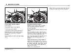
The suction line
5
remains in the crankcase. It
extends into the oil tank. To remove it, carefully
pull on the connection to the oil pump.
Removing the oil pump
Push the adjusting screw
6
up against the
spring pressure and turn it until the pin
7
goes
into the assembly slit
7
. If necessary press the
supply piston
8
in somewhat.
Note:
When assembling put the adjusting screw
6
counterclockwise to stop.
Removing the oil tank vent
Note:
The ventilation valve
9
must be punched
into the tank.
Press in a new valve about 2 mm deep under
the housing surface.
Make sure that the ventilation channel
10
is free
of deposits. Clean if necessary.
1
2
A
4
3
1
2
3
5
6
8
7
9
10
05 OIL PUMP
General
The oil pump is driven by the drive worm gear
1
on the crankshaft.
This gear engages the oil pump piston
3
.
Consequently, the oil pump operates only when
the engine is on.
The oil flow rate can be adjusted with adjusting
screw
A
:
• Turn right for more oil
• Turn left for less oil
Disassembly
Remove the clutch drum and clutch, see
chapter 04. Remove brake band, see chapter 03.
Move the drive worm gear
1
gently back and
forth and work it off the shaft.
Pull the oil pressure line
2
from the oil pump.
Unscrew screw
4
and remove the oil pump.
Flathead screw
No.: 165.888.110


