


P 1
0
/
18
R
epair
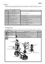
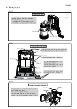
ASSEMBLING
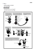
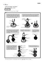
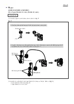
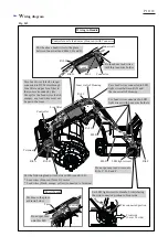
(3) Mount Ring spring 12 to Lever 54 as drawn in
Fig. 12
.
Using 1R242 as a guiding jig, set Ring spring 12 from the opposite side of Grip portion.
Note
: Refer to the following drawings for the proper direction of Ring spring 12.
Ring spring 12
Fig. 12
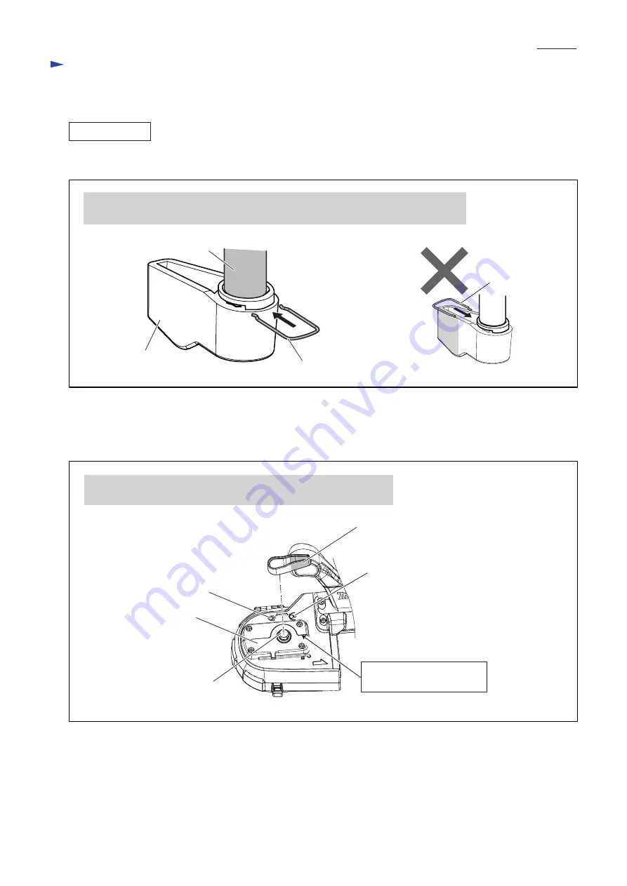
Fig. 13
Grip portion of Lever 54
Face the grip portion of Lever 54 to the release mark side, and mount
the lever to Lever shaft while aligning the lever to the guide line.
“Release mark”
“Tension mark”
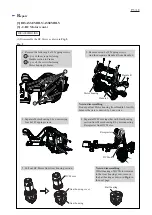
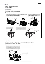
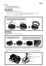
(4) Assemble Lever holder to Frame with four 4x18 Tapping screws. (Refer to the
upper right
drawing in
Fig. 10
)
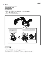
(5) Mount Lever 54 over Lever shaft as drawn in
Fig. 13
.
Lever shaft
Lever holder
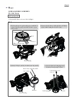
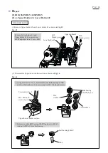
[3] DISASSEMBLY/ASSEMBLY
[3] -4. Lever Shaft (cont.)
Grip portion
1R242
Ring spring 12
Guide line for Lever setting
to release position


