


P
9
/
18
R
epair
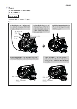
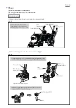
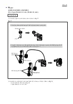
[3] DISASSEMBLY/ASSEMBLY
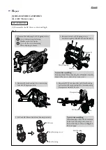
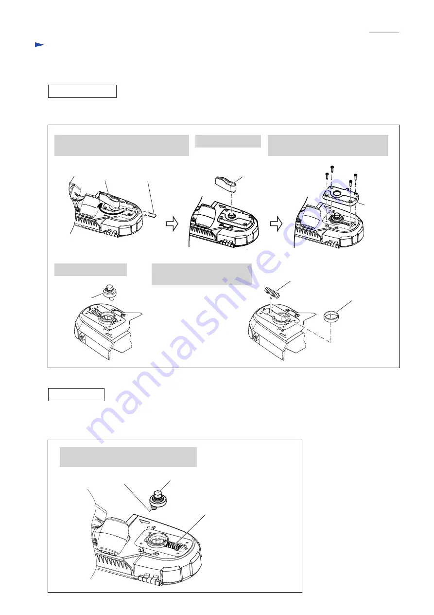
[3] -4. Lever Shaft
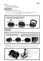
Fig. 10
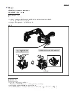
Fig. 11
DISASSEMBLING
ASSEMBLING
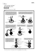
1. Pull off Ring spring 12 from the machine,
and set Lever 54 to the release position.
2. Pull off Lever 54.
4. Pull off Lever shaft.
5. Remove Plane bearing 30 and
Compression spring 30.
3. Remove Lever holder by unscrewing
four 4x18 Tapping screws.
(1) Disassemble Lever shaft as drawn in
Fig. 10
.
Lever
holder
Lever shaft
Plane bearing 30
Compression sprig 9
4x18 Tapping
screws
( 4 pcs. )
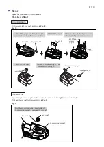
(1) Set Compression spring 9 and Plane bearing 30 as drawn to
the right
illustration in
Fig. 10
.
(2) Mount Lever shaft to Frame as drawn in
Fig. 11
.
Ring spring 12
Lever 54
Lever 54
Compression spring 9
Lever shaft
Pin portion
Face the pin portion to the opposite side of
Compression spring 9, and mount Lever shaft.


