11 ENGLISH
Hook
CAUTION:
Never hook the tool on a windy
location or a potentially unstable surface.
CAUTION:
Do not use the hook when it is
deformed or damaged.
CAUTION:
When not operating the tool,
always fold the hook.
The hook is convenient for hanging the tool temporarily.
►
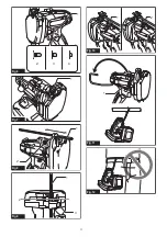
Fig.11:
1.
Hook
CAUTION:
Do not hang the hook from the
waist belt.
It may result in personal injuries and/or
damage to the tool if dropped.
►
Fig.12
Hex wrench storage
When not in use, store the hex wrench as shown in the
figure to keep it from being lost.
►
Fig.13:
1.
Hex wrench
Shoulder strap
Optional accessory
Shoulder strap is useful for carrying the tool.
►
Fig.14:
1.
Shoulder strap
2.
Belt end
3.
Buckle
CAUTION:
Always wear the shoulder strap
crossed over your body and adjusted in proper length.
CAUTION:
Do not use the shoulder strap if it
is damaged.
CAUTION:
Leave an sufficient length between
the buckle and belt end to prevent the belt end
from slipping through the buckle.
ASSEMBLY
CAUTION:
Always be sure that the tool is
switched off and the battery cartridge is removed
before carrying out any work on the tool.
Installing the cutting dice
CAUTION:
Always install the cutting dice in
the correct directions and secured firmly.
Incorrect
or loose attachment may cause breakage of the cutting
dice, resulting personal injury by flown off fractions.
NOTICE:
Remove the burr on the cutting dice
using a file if any.
1.
Check if the jaw of the cutting dice is fully opened.
If not, install the battery and pull the switch trigger until
the jaw is fully opened.
CAUTION:
Be sure to remove the battery
cartridge if you installed.
2.
Set the reversing switch lever to the lock position.
►
Fig.15:
1.
Reversing switch lever
3.
Unscrew the bolts with the supplied hex wrench.
CAUTION:
Use only the Makita wrench pro-
vided with the tool.
Using other wrenches may
result in overtightening or insufficient tightening which
causes personal injury.
4.
Set the cutting dice onto the mounts so that the
two colored markings can be seen.
►
Fig.16:
1.
Bolt
2.
Cutting die
3.
Stationary mount
4.
Movable mount
5.
Colored marking
6.
Hex wrench
5.
Secure the cutting dice with the bolts firmly.
The cutting dice are correctly installed if the arrows on them
point each other. The dimensions of the cutting dice are the
same but their thickness look different when seen from above.
►
Fig.17:
1.
Arrow
2.
Cutting die
3.
Thin side
4.
Thick side
OPERATION
CAUTION:
Make sure that the correct size of the
cutting dice are installed to the tool. Check the cutting
capacity written on the the cutting dice before cutting.
CAUTION:
Before pulling the switch trigger,
be sure to set the threaded rod so that its thread
fits with those of cutting dice.
Incorrect alignment
of the threads may break the cutting dice and cause
personal injury by flown off fractions.
CAUTION:
Replace the cutting dice if the
cutting edge is chipped or deformed.
When cutting, place the threaded rod perpendicular to
the cutting line as shown in the figure.
►
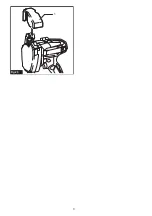
Fig.18:
1.
Cutting line
NOTE:
When cutting a threaded rod made of ductile
metal such as stainless steel, burrs may be generated
on the cut end. Remove burrs with a file in this case.
►
Fig.19:
1.
Threaded rod
2.
Burr
Cutting secured threaded rods
When cutting a threaded rod which is secured to the
building structure such as the ceiling, wall, floor, etc.,
follow the procedure below :
►
Fig.20:
1.
Threaded rod
2.
Cutting die on the sta-
tionary mount
1.
Bring the tool so that the threaded rod is posi-
tioned between the cutting dice.
2.
While the threaded rod contacting with the rod
guide, fit the thread of the rod with that of the cutting die
on the stationary mount.
3.
Pull and hold the switch trigger until the cutting is finished
and the jaw of the cutting dice comes to fully opened position.
NOTICE:
Clean the front face of the tool and the
tip of the guide scale before operation.
They may
dirty the contacting surface.
Summary of Contents for DSC102
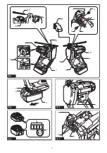
Page 2: ...13 14 5 7 12 9 11 10 6 15 8 1 2 3 4 4 Fig 1 1 2 3 Fig 2 1 2 Fig 3 1 Fig 4 1 2 3 Fig 5 2 ...
Page 3: ...1 2 3 4 Fig 6 1 Fig 7 1 2 Fig 8 2 1 3 Fig 9 2 1 Fig 10 1 Fig 11 Fig 12 3 ...
Page 4: ...1 Fig 13 1 2 3 2 Fig 14 1 Fig 15 1 1 2 2 5 3 6 4 Fig 16 1 2 3 4 Fig 17 1 Fig 18 4 ...
Page 5: ...1 2 Fig 19 1 2 Fig 20 1 2 Fig 21 4 1 2 3 Fig 22 1 2 Fig 23 1 2 3 Fig 24 5 ...
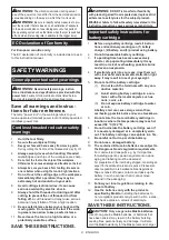
Page 6: ...1 Fig 25 6 ...
Page 79: ...79 ...


