12 ENGLISH
Cutting loose threaded rods
When cutting a loose threaded rod on the floor or a
work table, follow the procedure below :
►
Fig.21:
1.
Threaded rod
2.
Cutting die on the sta-
tionary mount
1.
Position a threaded rod between the cutting dice.
2.
While the threaded rod contacting with the rod
guide, fit the thread of the rod with that of the cutting die
on the stationary mount.
3.
Pull and hold the switch trigger until the cutting is
finished and the jaw of the cutting dice comes to fully
opened position.
When cutting a long threaded rod which is hard to hold
by hand, place the tool as illustrated. The tool can be
placed flat. The cover also can be used for supporting
the end of the threaded rod.
►
Fig.22:
1.
Cover (Position 1)
2.
Rod guide (Position
1)
3.
Cover (Position 2)
4.
Rod guide
(Position 2)
The cover has markings to indicate its position.
Depending on the size of the threaded rod, put the
cover in the position as shown in the table as well as the
rod guide.
Position
Size of threaded rod
1
W3/8, 3/8-16UNC, M10
2
W5/16, W1/4, 5/16-18UNC, 1/4-20UNC,
M8, M6
Quitting the cutting in the middle
CAUTION:
Never try to pull out the tool forci-
bly from the threaded rod.
It may cause unexpected
start up which cause personal injury or damage to the
cutting dice and tool.
When quitting the cutting in the middle, set the revers
-
ing switch lever to the reversing position and pull the
switch trigger until the threaded rod is completely
released from the cutting dice.
MAINTENANCE
CAUTION:
Always be sure that the tool is
switched off and the battery cartridge is removed
before attempting to perform inspection or
maintenance.
NOTICE:
Never use gasoline, benzine, thinner,
alcohol or the like. Discoloration, deformation or
cracks may result.
Replacing the cutting dice
NOTICE:
Replace the both cutting dice at the
same time.
Replacing the one side of the cutting die
may generate burr on the threaded rod.
Replace the cutting dice when it is chipped, deformed,
or the cutting gets dull. To replace, follow the instruc-
tions in "Installing the cutting dice".
►
Fig.23:
1.
Chipping
2.
Deformation
One cutting die has two cutting edges and thick side
and thin side. Switch the installation positions of the
cutting dice if you have not used the other sides of the
cutting edges.
►
Fig.24:
1.
Cutting edge
2.
Thin side
3.
Thick side
Carrying/storing the tool
CAUTION:
When the tool is not used, always
attach the supplied cover to the cutting portion.
Attach the cover when carrying the tool.
When storing the tool, remove the battery cartridge and
the guide scale from the tool. Clean dust on the cutting
dice and the moving part. After that, attach the cover.
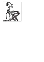
►
Fig.25:
1.
Cover
To maintain product SAFETY and RELIABILITY,
repairs, any other maintenance or adjustment should
be performed by Makita Authorized or Factory Service
Centers, always using Makita replacement parts.
OPTIONAL
ACCESSORIES
CAUTION:
These accessories or attachments
are recommended for use with your Makita tool
specified in this manual.
The use of any other
accessories or attachments might present a risk of
injury to persons. Only use accessory or attachment
for its stated purpose.
If you need any assistance for more details regard
-
ing these accessories, ask your local Makita Service
Center.
•
Cutting dice
•
Shoulder strap
•
Makita genuine battery and charger
NOTE:
Some items in the list may be included in the
tool package as standard accessories. They may
differ from country to country.
Summary of Contents for DSC102
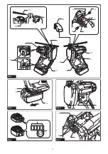
Page 2: ...13 14 5 7 12 9 11 10 6 15 8 1 2 3 4 4 Fig 1 1 2 3 Fig 2 1 2 Fig 3 1 Fig 4 1 2 3 Fig 5 2 ...
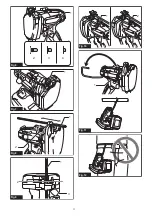
Page 3: ...1 2 3 4 Fig 6 1 Fig 7 1 2 Fig 8 2 1 3 Fig 9 2 1 Fig 10 1 Fig 11 Fig 12 3 ...
Page 4: ...1 Fig 13 1 2 3 2 Fig 14 1 Fig 15 1 1 2 2 5 3 6 4 Fig 16 1 2 3 4 Fig 17 1 Fig 18 4 ...
Page 5: ...1 2 Fig 19 1 2 Fig 20 1 2 Fig 21 4 1 2 3 Fig 22 1 2 Fig 23 1 2 3 Fig 24 5 ...
Page 6: ...1 Fig 25 6 ...
Page 79: ...79 ...


