background image

1 / 19

Model No.
Description

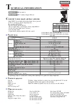
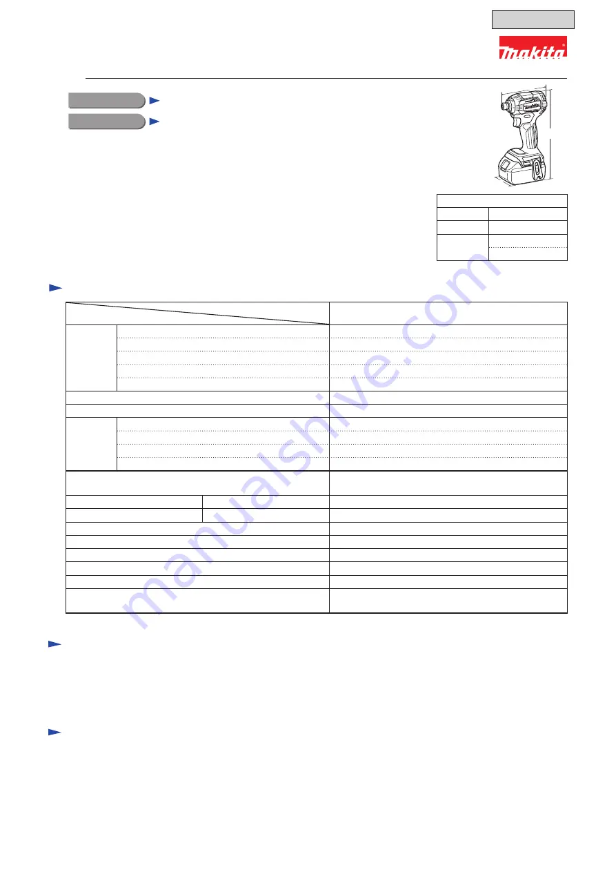
Cordless Impact Driver

DTD170

C

ONCEPT AND MAIN APPLICATIONS

Model DTD170 is our high-end Cordless impact driver powered 

by 18V Li-ion battery and developed based on

the current model DTD148.

The main features and benefits are:

• More compact body (overall length: 117mm) than DTD148

• Electronic 4 stage impact power selection

• A mode [assist mode]

• Ergonomically designed handle with better control

S

pecifications

Model

Specifications

DTD170

Battery

Voltage: V

18

Capacity: Ah

1.5, 2.0, 3.0, 4.0, 5.0, 6.0

Energy capacity: Wh

27, 36, 54, 72, 90, 108

Cell

Li-ion

Charging time (approx): min

15, 24, 22, 36, 45, 55 with DC18RC

Max output (W)

290

Driving shank: mm (")

6.35 (1/4) Hex

Capacities

Machine screw

M4 - M8 (5/32 - 5/16")

Standard bolt

M5 - M16 (3/16 - 5/8")

High strength bolt

M5 - M14 (3/16 - 9/16")

Coarse-thread

22 - 125mm (7/8 - 4-7/8")

Impact power selection

Electronic 4 stage (Max/ Hard/ Medium/ Soft)

+ Teks screw mode + A mode [assist mode]

Impacts per min: min

-1

=ipm

Max/ Hard/ Medium/ Soft

0 - 3,800/ 3,600/


2,600/ 1,100

No load speed: min

-1

=rpm

Max/ Hard/ Medium/ Soft

0 - 3,600/ 3,200/ 2,100/ 1,100

Max tightening torque

*

3

: N·m [kgf·cm] (in·lbs)

175 [1,780] (1,550)

Electric brake

Yes

Variable speed control by trigger

Yes

Reverse switch

Yes

LED job light

Yes

Weight according to

EPTA-Procedure 01/

ver.2.1

: kg(lbs)

1.2 (2.7)

*

1

 or 1.5 (3.3)

*

2

*3

 Tightening torque at 3 seconds after seating, when tightening M16 (grade 10.9) high strength bolt

Dimensions: mm ( " )

Length (L)

117 (4-5/8)

Width (W)

79 (3-1/8)

Height (H) 218 (8-5/8)

*

1

236 (9-1/4)

*

2

*1

 With Battery BL1815N, BL1820(B)

*2

 With Battery BL1830(B), BL1840(B), BL1850(B),  


BL1860B

Belt clip

Battery

*

5

Battery cover

*

6

Charger

*

5

Plastic carrying case

*

5

*5

 Battery, charger and plastic carrying case are not supplied with “Z” model.

*6

 Supplied with the same quantity of extra Battery.

Note:

 The standard equipment may vary by country or model variation.

Phillips bits

Socket bits

Drill chucks

Drill bits with 6.35mm Hex shank

Bit piece

Stopper for impact driver

Hook set (Belt clip)

Tool catcher set

Battery protectors

Li-ion batteries:

BL1815N, BL1820(B), 

BL1830(B), BL1840(B),

BL1850(B), BL1860B

Fast charger DC18RC

Two port multi fast charger DC18RD

Charger DC18SD/DC24SC

Four port multi charger DC18SF

Automotive charger DC18SE

S

tandard equipment

O

ptional accessories

H

W

L

July 2016

T

ECHNICAL INFORMATION

OFFICIAL USE 

for ASC & Sales Shop

Summary of Contents for DTD170

Page 1: ...100 1 100 Max tightening torque 3 N m kgf cm in lbs 175 1 780 1 550 Electric brake Yes Variable speed control by trigger Yes Reverse switch Yes LED job light Yes Weight according to EPTA Procedure 01...

Page 2: ...ing 9 5 2 2 Assembling 9 5 3 Anvil N 11 5 3 1 Disassembling 11 5 3 2 Assembling 11 5 4 Hammer section 12 5 4 1 Disassembling 12 5 4 2 Assembling 13 6 Circuit diagram 14 6 1 How to disassemble Stator 1...

Page 3: ...212 A Tip for retaining ring pliers use with 1R003 1R212 B Plate set with screws 1R223 Torque wrench shaft 20 90N m assembling Hammer case complete 1R224 Ratchet head 12 7 use with 1R223 1R232 Pipe 30...

Page 4: ...ng screws and then remove Housing R Fig 5 1 1 1 1 Remove two Bind PT 3x16 Tapping screws and remove Rear cover Fig 5 1 1 2 2 Mount 1R016 to the machine and fix it with Vise Remove Rotor by prying it o...

Page 5: ...ammer case complete Note To remove Hammer case cover Hammer case complete must be removed from Housing L in advance Fig 5 1 1 5 5 Remove Bumper with a small slotted screwdriver Fig 5 1 1 4 4 Remove Ha...

Page 6: ...2 50 with Vise and two 1R040 and set Bearing box complete to Socket 32 50 Socket 30 78 Nut spinner handle Hammer case complete Fig 5 1 1 9 9 Hammer case complete section can be disassembled as shown b...

Page 7: ...se with 1R224 and Socket 30 78 Fig 5 1 2 2 3 Fix Socket 32 50 with Vise and two 1R040 and set Bearing box complete to Socket 32 50 Projection Thin washer 15 Note Be careful not to lose it Internal gea...

Page 8: ...cover to Hammer case complete as shown below U shape notch Stopper portion Projection Hammer case cover Groove on Bumper Groove on Hammer case cover Fig 5 1 2 7 8 Assemble Housing R to Housing L with...

Page 9: ...tor When handling or storing multiple Rotors be sure to keep a proper distance between Rotors as shown in Fig 5 2 2 1 Because Rotor has strong magnetic force failure to follow this instruction could r...

Page 10: ...projections on Housing L Fig 5 2 2 4 4 Make sure that Stator is properly assembled to Housing L Fig 5 2 2 5 5 Set the convex portion of Switch to the concave portion of F R Change lever Housing L Stat...

Page 11: ...1 2 3 Remove Ring spring 11 while checking the following points Press the top of Bit sleeve with a thumb so as not to pop out Compression spring 13 Expand the end gap of Ring spring 11 with 1R003 1R2...

Page 12: ...rtion with the top of Cam grooving on Spindle by turning 1R045 5 Remove two Steel balls 5 6 with Tweezers or Magnetic screwdriver 6 Turn 1R045 clockwise to release Hammer case section 1R045 Hammer Spi...

Page 13: ...embling Before assembling Steel balls 3 5 check the following points Twenty four Steel balls 3 5 are put in the groove of Hammer as shown below There is a gap equivalent to the size of one Steel ball...

Page 14: ...with lock 187 t 0 8mm Sensor board 1 Remove Sensor board from Stator by removing three PT 2x6 Tapping screws with No 1 Phillips screwdriver 2 Remove three M3x6 Flat head screws with No 1 Phillips scr...

Page 15: ...e complete Boss LED circuit Rib A Rib B F R Change lever Cross section of A Projection of Hammer case complete Hammer case complete Area 1 Area 2 2 Do not put the lead wires of LED circuit on Area 1 a...

Page 16: ...res on Switch Pass the lead wires of Stator and LED circuit between the rib D and rib E Rib E Rib D Switch LED circuit Controller Terminal Do not put any Lead wires on these Ribs Put the controller le...

Page 17: ...ing 10 times F R change lever Switch plate Variable speed control trigger 8 2 Test for recognizing the short circuit of FET Field Effect Transistor on controller Trouble on Controller can be checked w...

Page 18: ...lace Controller LED job light are on Lead wires are broken Check Lead wires or replace them LED circuit is broken Replace LED circuit Switch is broken Replace Switch Yes Yes Switch is broken Replace S...

Page 19: ...ping screw 1 1 1 3 8 2 Rear cover Housing R L Bind PT 3x16 Tapping screw 1 1 1 3 2 3 Controller terminal unit Stator M3x6 Flat head screw 0 4 0 6 3 4 Controller print board Stator PT 2x6 Tapping screw...

Reviews: