


12 ENGLISH
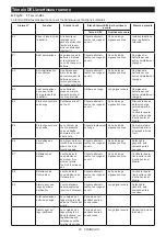
Alarm No.
Function
Status of the tool
Status of the LED indicator/beeper
Action to be taken
LED indicator
Beeper
-
Auto-stop with fas-
tening completion
The preset fasten-
ing torque has been
achieved and the
tool has stopped.
Lights up in green
for approximately
one second.
–
–
-
Alarm for insufficient
fastening
The preset fas-
tening torque has
not been achieved
because the switch
trigger was released
before completing
the fastening.
Lights up in red for
approximately one
second.
A long beep
Retighten the
fastener.
-
Alarm for limit of the
fastening capacity
–
Blinks in red quickly.
A series of long
beeps
Replace the battery
with fully charged
one.
-
Maintenance alarm
The number of drive
has been reached to
your preset number
for the maintenance.
Blinks in yellow.
–
Reset the alarm
with the application
software.
-
Alarm for no com-
munication with
the PC
No data commu-
nication while the
tool is connected to
the PC.
Blinks in yellow.
–
Restart the appli-
cation software and
re-connect the USB
cable.
-
Indication that the
tool can communi-
cate with the PC
The tool is con-
nected to the PC
and able to commu-
nicate with.
Blinks in green.
–
–
-
Check for the lamp
and beeper (when
the battery cartridge
is installed)
The tool performs
the operation test
for the LED indicator
(green/red), light,
and beeper.
The LED indicator
lights up in green
and then red. After
that, the light turns
on for a while.
A series of very
short beeps
–
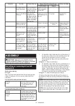
ASSEMBLY
CAUTION:
Always be sure that the tool is
switched off and the battery cartridge is removed
before carrying out any work on the tool.
Installing or removing driver bit/
socket bit
Optional accessory
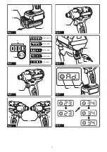
►
Fig.13
Use only driver bit/socket bit that has inserting portion
shown in the figure. Do not use any other driver bit/
socket bit.
For tool with shallow driver bit hole
A=12mm
B=9mm
Use only these type of driver
bit. Follow the procedure
1. (Note) Bit-piece is not
necessary.
For tool with deep driver bit hole
A=17mm
B=14mm
To install these types of driver
bits, follow the procedure 1.
A=12mm
B=9mm
To install these types of driver
bits, follow the procedure 2.
(Note) Bit-piece is necessary
for installing the driver bit/
socket bit.
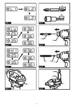
1. To install the driver bit/socket bit, pull the sleeve in
the direction of the arrow and insert the driver bit/
socket bit into the sleeve as far as it will go.
Then release the sleeve to secure the driver bit/
socket bit.
►
Fig.14:
1.
Driver bit
2.
Sleeve
2. To install the driver bit/socket bit, pull the sleeve in
the direction of the arrow and insert the bit-piece
and driver bit/socket bit into the sleeve as far as it
will go. The bit-piece should be inserted into the
sleeve with its pointed end facing in. Then release
the sleeve to secure the driver bit/socket bit.
►
Fig.15:
1.
Driver bit
2.
Bit-piece
3.
Sleeve
To remove the driver bit/socket bit, pull the sleeve in
the direction of the arrow and pull the driver bit/socket
bit out.
NOTE:
If the driver bit/socket bit is not inserted deep
enough into the sleeve, the sleeve will not return to its
original position and the driver bit/socket bit will not
be secured. In this case, try re-inserting the driver bit/
socket bit according to the instructions above.
NOTE:
After inserting the driver bit/socket bit, make
sure that it is firmly secured. If it comes out, do not
use it.
Summary of Contents for DTDA040 Series
Page 3: ...Fig 9 Fig 10 Fig 11 1 Fig 12 Fig 13 2 1 Fig 14 3 2 1 Fig 15 2 2 1 Fig 16 3 ...
Page 4: ...Fig 17 4 ...
Page 122: ...122 ...
Page 123: ...123 ...