15 ENGLISH
1.
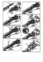
Remove three screws (for DUH504S), four screws
(for DUH604S) or five screws (for DUH754S), and then
remove the chip receiver from the tool.
►
Fig.7:
1.
Chip receiver
2.
Screw
2.
Place the tool upside down, and then remove six
bolts.
►
Fig.8:
1.
Bolt
3.
Remove the cover and the plate.
►
Fig.9:
1.
Cover
2.
Plate
NOTE:
The plate may remain on the cover.
4.
Remove the rod and the bearing.
►
Fig.10:
1.
Rod
2.
Bearing
NOTE:
The rod or bearing may remain on the cover.
5.
Remove three screws, three sleeves and the felt
pad, and then remove the shear blades.
►
Fig.11:
1.
Screw
2.
Sleeve
3.
Felt pad
4.
Shear
blades
NOTICE:
Be careful not to lose the screws.
6.
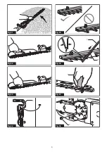
Remove the blade cover, and then attach it to the
new shear blades.
►
Fig.12
7.
Adjust the crank so that two holes are lined up on
the alignment line.
►
Fig.13:
1.
Hole
2.
Alignment line
8.
Align the protrusions on the shear blades vertically
at the same position.
►
Fig.14:
1.
Protrusion
9.
Insert the screw removed in step 5 into the hole
on the shear blades to temporarily fix the shear blades,
and then attach the felt pad to the shear blades.
►
Fig.15:
1.
Screw
2.
Felt pad
3.
Hole
10.
Insert the protrusion on the shear blades to the
hole on the rod, then align the position of the felt pad
with the holes on the tool. Attach two new sleeves.
►
Fig.16:
1.
Felt pad
2.
Protrusion
3.
Hole
4.
Sleeve
NOTICE:
Apply a small amount of grease to the
inner periphery of the hole of the rod.
NOTICE:
Be careful not to lose the sleeves.
11.
Align the holes on the sleeves, and shear blades
with the holes on the tool, and then tighten two screws
to temporarily fix the shear blades.
►
Fig.17:
1.
Screw
12.
Attach a new sleeve.
►
Fig.18:
1.
Sleeve
13.
Remove the screw inserted into the hole on the
shear blades in step 9, and then tighten the screw
together with the sleeve to fix the shear blades.
►
Fig.19:
1.
Screw
14.
Firmly tighten the screws which were temporarily
fixed in step 11.
15.
Attach the bearing and the rod.
►
Fig.20:
1.
Rod
2.
Small hole
3.
Bearing
NOTICE:
Apply a small amount of grease to the
inner periphery of the small hole of the rod.
NOTICE:
Make sure that the protrusion on the
shear blades fits in the small hole on the rod.
16.
Attach the plate.
►
Fig.21:
1.
Protrusion
2.
Plate
NOTICE:
Make sure that the protrusion on the
shear blades fits in the hole on the plate.
17.
Attach the cover, and then tighten six bolts.
►
Fig.22:
1.
Bolt
2.
Cover
18.
Attach the chip receiver to the tool by tighten
-
ing three screws (for DUH504S), four screws (for
DUH604S) or five screws (for DUH754S).
►
Fig.23:
1.
Chip receiver
2.
Screw
NOTICE:
If the shear blades do not move
smoothly, the shear blades are not engaged with
the rods properly. Install the shear blades again.
NOTICE:
If the parts other than the shear
blades such as the rods are worn out, ask Makita
Authorized Service Centers for parts replacement
or repairs.
Removing or installing the chip
receiver
CAUTION:
When installing or removing the
chip receiver, always wear gloves so that your
hands do not directly contact the shear blades.
The chip receiver gathers discarded leaves and makes
clean-up afterward much easier.
To remove the chip receiver, remove three screws (for
DUH504S), four screws (for DUH604S) or five screws
(for DUH754S), and then remove the chip receiver from
the tool. To install the chip receiver, follow the removal
procedure in reverse.
►
Fig.24:
1.
Chip receiver
2.
Screw
Summary of Contents for DUH504S
Page 2: ...1 2 3 Fig 1 1 2 Fig 2 1 2 Fig 3 1 2 Fig 4 2 1 3 Fig 5 2 1 Fig 6 2 1 Fig 7 1 Fig 8 2 ...
Page 3: ...1 2 Fig 9 1 2 Fig 10 2 1 3 4 Fig 11 Fig 12 1 2 Fig 13 1 Fig 14 1 2 3 Fig 15 3 ...
Page 4: ...1 2 3 4 Fig 16 1 Fig 17 1 Fig 18 1 Fig 19 1 2 3 Fig 20 1 2 Fig 21 1 2 Fig 22 4 ...
Page 5: ...2 1 Fig 23 2 1 Fig 24 1 2 Fig 25 Fig 26 Fig 27 Fig 28 Fig 29 Fig 30 5 ...
Page 6: ...Fig 31 Fig 32 Fig 33 1 Fig 34 Fig 35 1 2 Fig 36 1 Fig 37 1 Fig 38 6 ...
Page 7: ...2 1 Fig 39 7 ...


