24 / 71
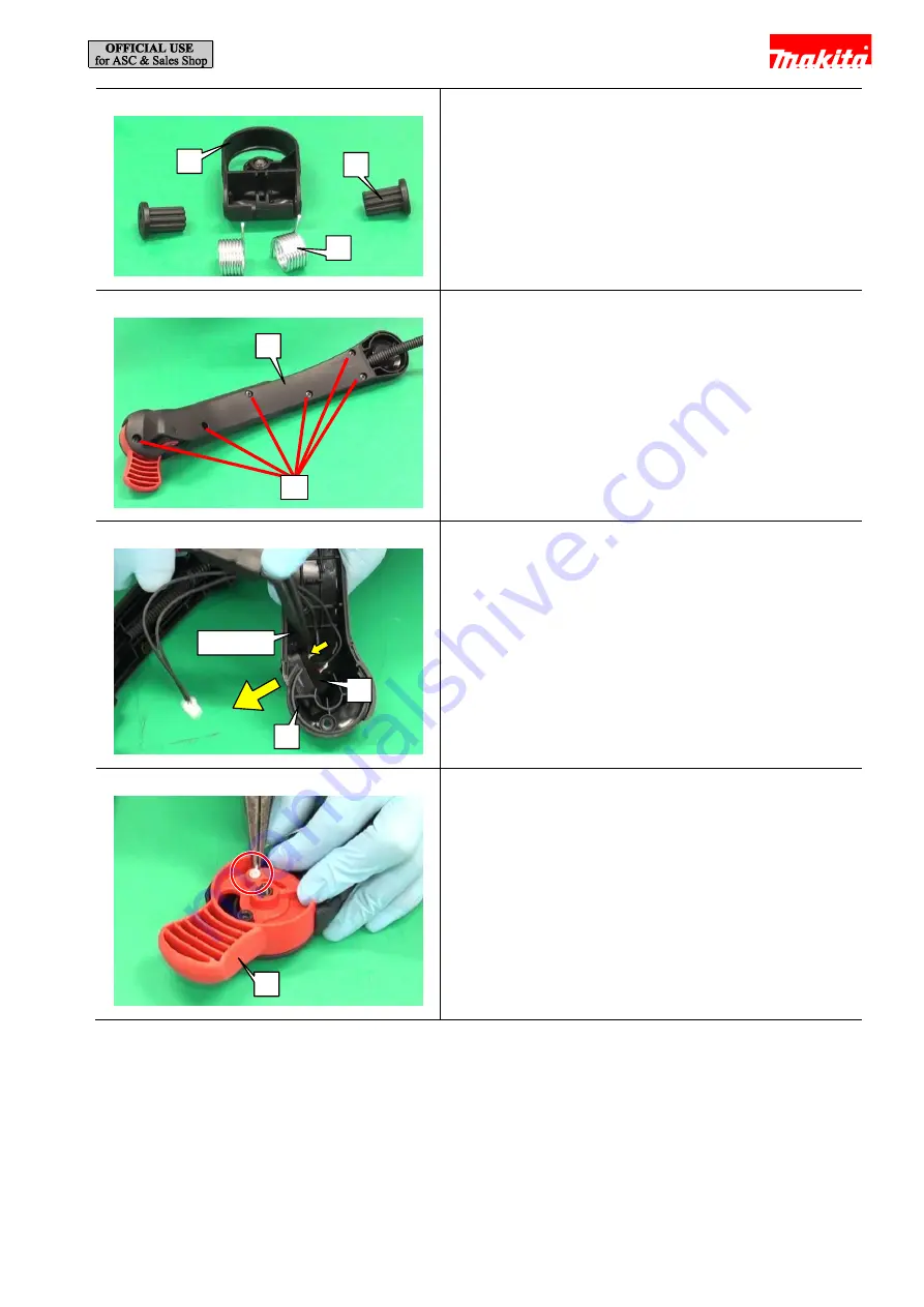
Fig. 52
6
Remove two Rubber sleeves 6 [2] from Arm base [1].
and then remove two Torsion springs 21 [3].
Fig. 53
7
Remove six 4x18 Tapping screws [1] to remove Arm
cover [2].
Fig. 54
8
Disconnect the connector of Lead unit, and then push
Switch unit [1] out of Arm cover [2] with 1R311.
Fig. 55
9
Remove Corrugated tube, and then disconnect the
barrel nipple of Control cable from Throttle lever [1].
[1]
[2]
1R311
[1]
[2]
[1]
[1]
[2]
[3]


