70 / 71
7-2
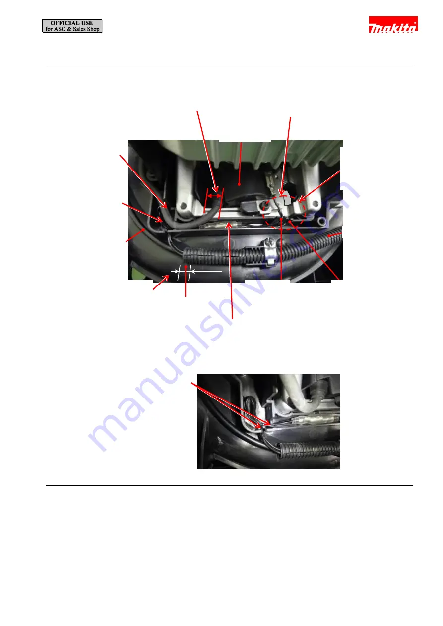
Front volute case section
Fig. 160
Ignition coil
The high-voltage cable should be
routed in this space.
The lead wires should
be tight between
Ignition coil and Lead
wire holder A/B.
Corrugated tube
Lead wire
holder A
Lead wire
holder B
The straight terminal should be
put in this space.
Projection A
Controller lead
wire
Put the slack of the
lead wires from Leaf
spring A/B in this
space.
The high-voltage cable
should be routed over
the other lead wires.
The end of Corrugated tube
should be put within a 5mm
radius from the projection A.
±
5mm
The lead wires from Leaf spring A/B should
be deeply put into these lead wire holders.
Lead unit A from Ignition coil should be
deeply put into Lead wire holder A.
Lead unit B from Ignition coil should be
deeply put into Lead wire holder B.


