
March 2016
T
ECHNICAL INFORMATION
OFFICIAL USE
for ASC & Sales Shop
C
ONCEPT AND MAIN APPLICATIONS
Straight gasoline (lead-free gasoline for automobiles)
Nylon cutting head
0.5
24.5
Fuel tank capacity: L
Standard cutting tool
Engine Displacement: mL
Fuel
4-stroke
Specification
EBH252L
Model
Type
Starting system
Recoil starter, with mechanical decompression
Loop handle
Handle style
Engine oil
Carburetor
SAE10W-30 oil
in the Class SF or higher of API Classification
Diaphragm
Net weight
*
2
: kg (lbs)
5.2 (11.5)
*1
No load speed of the engine when installed on the brushcutter
*2
Dry weight, without universal guard, cutting tool and shoulder harness
Rapid start
Nylon cutting head
EBH253L
EBH253U
Loop handle
5.3 (11.7)
No
230mm (9")
diameter
4-tooth star blade
EBH252U
Bike handle
5.7 (12.6)
No
No
230mm (9")
diameter
4-tooth star blade
9,000
No load speed
*
1
: min-
ı
= rpm
9,000
10,000
10,000
Bike handle
5.9 (13.0)
Yes
Yes
Waist cushion
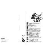
620 (24-3/8)
330 (13)
L
W
H
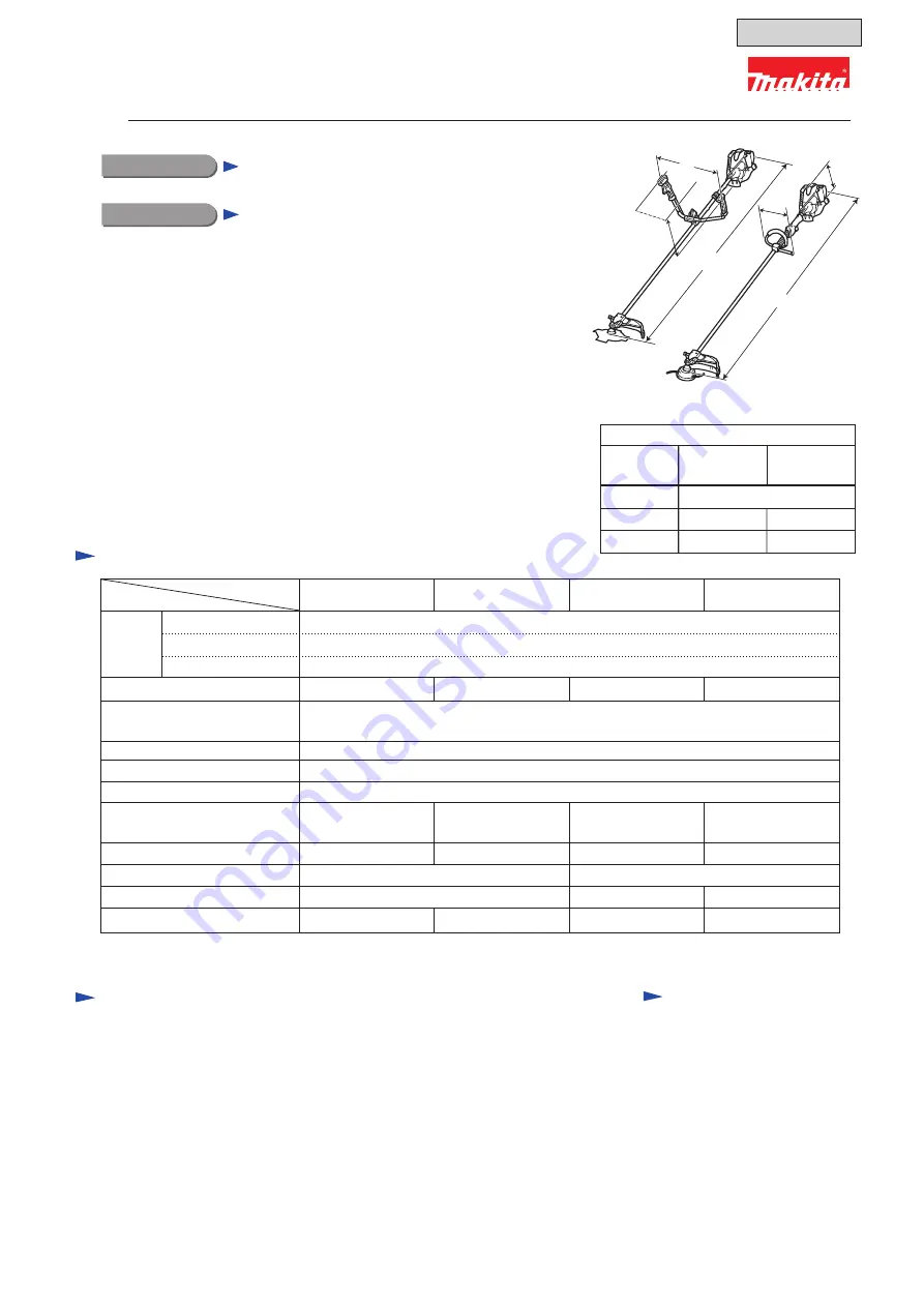
Dimensions: mm (")
Width (W)
Height (H)
Length (L)
1,770 (69-3/4)
490 (19-1/4) 265 (10-3/8)
EBH252U
EBH253U
EBH252L
EBH253L
EBH252U
EBH253U
EBH252L
EBH253L
L
W
H
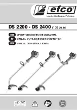
EBH252U, EBH252L
EBH253U, EBH253L
Petrol Brushcutter
These four models are 4-stroke petrol brushcutters developed
in compliance with EU Stage 2 exhaust emission regulations.
Their main features are:
• 4-stroke engine for low noise and clean exhaust emission
• Ergonomic handle for higher maneuverability
See “Specification” below for the specification differences
between the four models.
Note:
These four products are not in compliance with
the regulations of San Dimas.
1 / 40
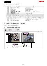
Model No.
Description
S
pecification
S
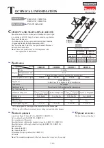
tandard equipment
Blades, Nylon cutting head
O
ptional accessories
Note:
The standard equipment for the tool shown above may vary by country.
4-tooth star blade 230mm (9") (for EBH252U, EBH253U)
Nylon cutting head (for EBH252L, EBH253L)
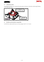
Universal guard (=Protector)
Shoulder harness with double shoulder straps (for EBH252U, EBH253U)
Shoulder harness with single shoulder strap (for EBH252L, EBH253L)
Socket wrench
Hex wrench (for M5)
Hex wrench (for M6)
Wire clamp (for tying cables) (for EBH252U)
Oil bottle