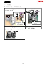
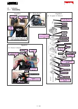
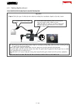
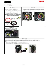
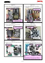
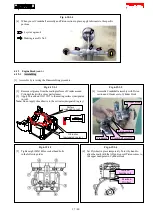
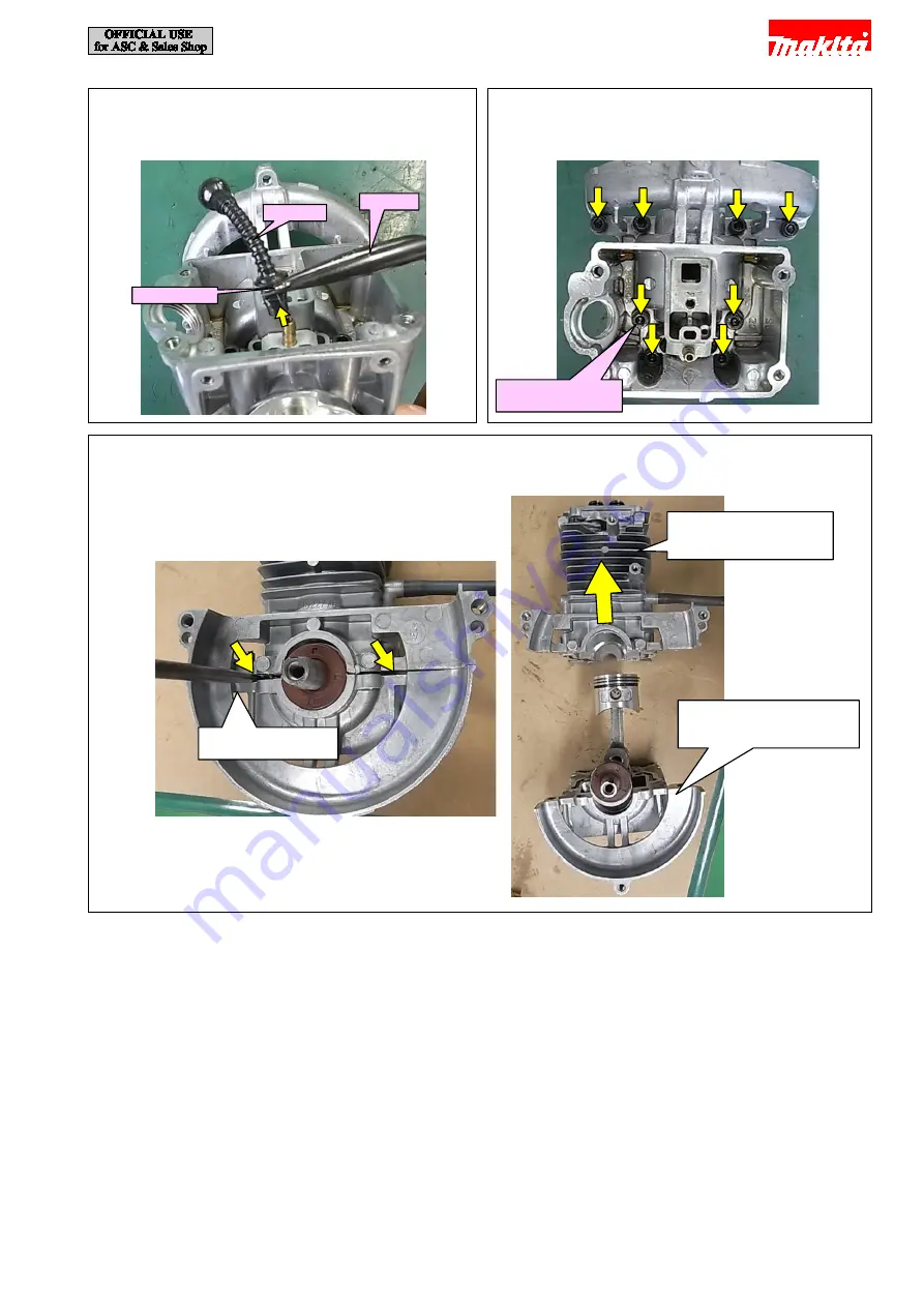
Fig. 6-17-1-9
[10] Remove Oil tube by loosening Hose clamp with 1R311.
1R311
Oil tube
Hose clamp
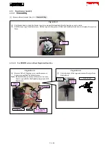
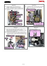
Fig. 6-17-1-10
[11] Loosen eight M5x14 Hex socket head bolts that fasten
Crankcase to Cylinder block.
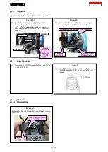
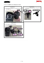
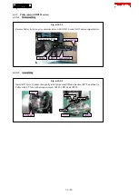
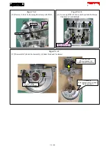
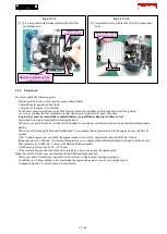
Fig. 6-17-1-11
[12] Disassemble Cylinder block assembly (Cylinder block and Crankcase).
Pry it off with a
slotted screwdriver.
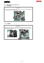
Cylinder block
(The component of
Cylinder block assembly)
Crankcase
(The component of Cylinder
block assembly)
M5x14 Hex socket
head bolt (8 pcs.)
34 / 40