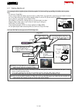
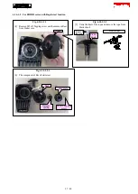
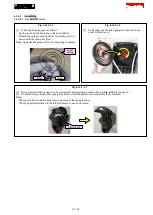
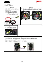
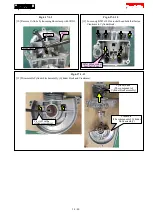
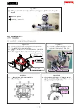
Fig. 6-19-1-7
[9] Insert 0.1mm feeler gauge of 1R366 into the clearance between
Rocker arm assembly and Intake/ exhaust valve holes.
Tighten the Rocker arm adjusting screws until the gauge is caught
with the Rocker arms and the valves.
Note:
After that, turn Crankshaft two revolutions by hand to do fine
adjustment of Rocker arm positions at the upper dead point until
the 0.1mm feeler gauge can be passed and 0.15mm feeler gauge
cannot.
0.1mm feeler
gauge of 1R366
Hex wrench 2.5
Off-set wrench 8
Rocker arm assembly
Pin 5
Apply 4 cycle engine oil
to the holes for Pin 5.
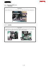
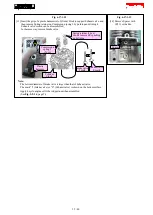
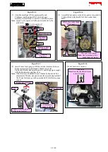
Fig. 6-19-1-8
[10] Set Lead valve in place.
Oil gauge
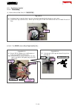
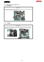
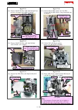
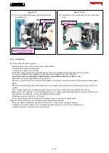
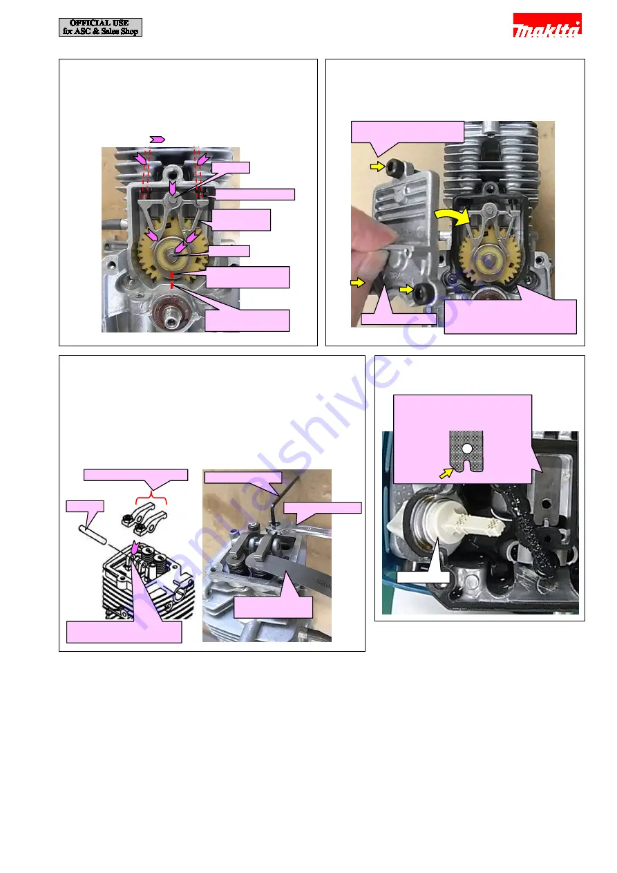
Fig. 6-19-1-6
[8] Assemble Cam gear cover and Cam gear cover gasket to
Cylinder block with three M5x14 Hex socket head
bolts.
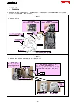
Fig. 6-19-1-5
[7] Align the markings of Cam gear assembly and
Crankcase, and then insert Pin 5 into Cam gear
assembly. Set two Rods 2.5 and two Cam lifter in place.
Note:
Apply 4 cycle engine oil to the positions shown by the
pink arrow.
M5x14 Hex socket head
bolt (3 pcs.)
Cam gear cover
Cam gear cover gasket
Note:
The orientation of the
gasket does not matter.
Marking on Cam
gear assembly
Marking on
Crankcase
Pin 5
Cam lifter
(2 pcs.)
Pin 4
Rod 2.5 (2 pcs.)
4 cycle engine oil
Lead valve
Note:
Face the chamfered corner
toward Oil gauge.
38 / 40