


13
PUTTING INTO OPERATION
CAUTION:
Always turn off the engine and pull off the spark plug cap
before doing any work on the Power Cutter! Always wear
protective gloves!
CAUTION:
Start the Power Cutter only after complete assembly and
inspection.
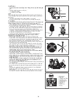
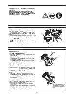
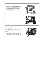
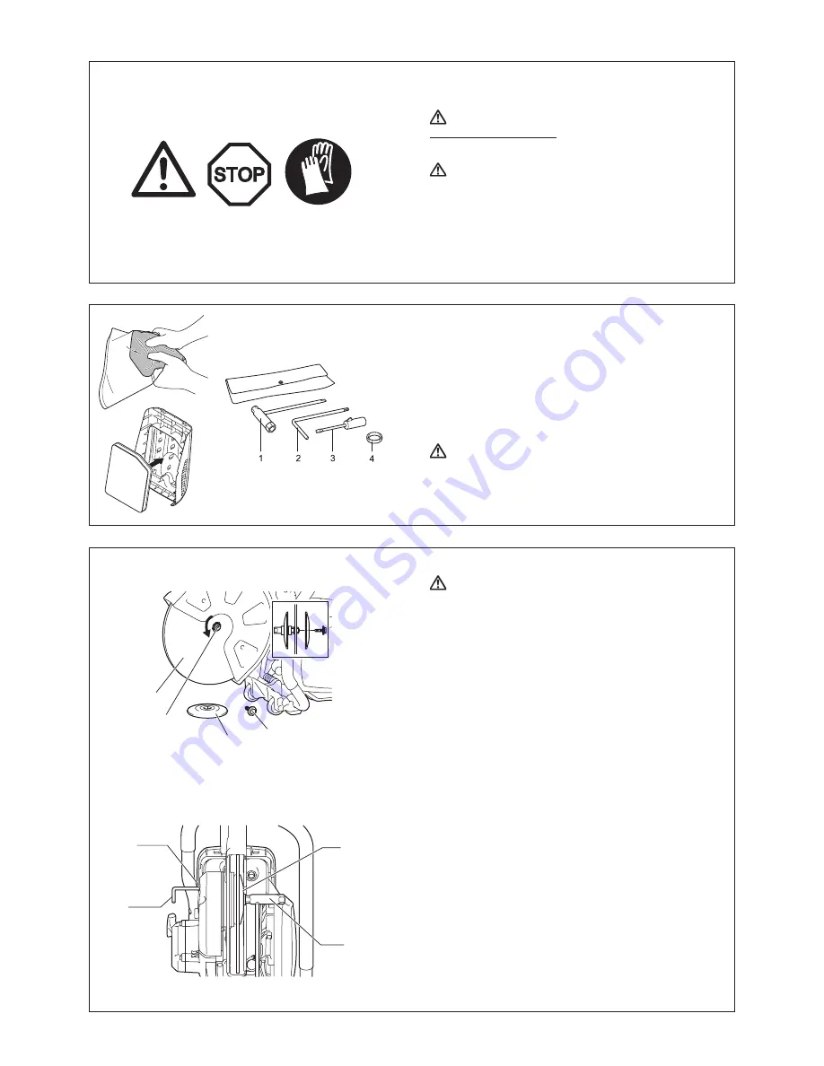
Mounting the cutting disc
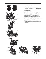
WARNING:
When installing a diamond cutting disc, be sure to mount
•
it so that the arrow is in the same direction as the outer
flange (6) rotates.
Mounting the diamond cutting disc
(4)
with
its arrow direction opposite to that on the wheel cover may
cause chipping of the disc edge and personal injury.
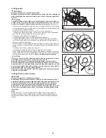
When installing a cutting disc (4), always use the ring that
•
matches the bore of the cutting disc and the diameter of
the spindle (5).
Failure to use rings that mate may cause tool
vibration resulting in serious personal injury.
Only use cutting discs with the bore that matches the
•
diameter of the ring(s) provided.
Using discs that do not mate
may cause tool vibration resulting in serious personal injury.
Inspect a cutting disc for damage. (see the section titled
•
“Cutoff discs” in SAFETY PRECAUTIONS.)
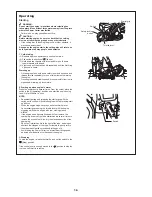
1. Insert the star-shaped wrench
(2)
into the hole
(8)
to prevent
the spindle
(5)
from rotating.
NOTE
: When the holder of the pressure water system is installed
in the hole in the tool, remove it before mounting the
cutting disc.
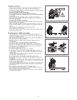
2. While holding on the wrench
(2)
in that position, use the
combination wrench
(1)
provided and turn the bolt
(7)
securing
the disc counterclockwise and remove the bolt
(7)
and outer
flange
(6)
.
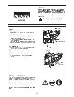
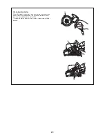
3. Mount a diamond cutting disc/cut-off abrasive disc
(4)
on the
arbor
(5)
. And then put the outer flange
(6)
on the spindle
so that the two parallel flat surface on the outer flange fit the
spindle flat surface and firmly tighten the bolt clockwise.
To install a cutting disc, mount a ring with the same matching
diameter as the disc bore and the O ring provided to retain the
ring on the spindle before installing a diamond cutting disc.
And then install the cutting disc.
NOTE
: Tighten the hex bolt firmly (25 - 31 Nm), as otherwise the
cutting wheel may slip during cutting.
4
5
6
7
6
1
8
2
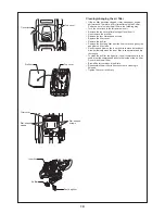
Schematic
drawing
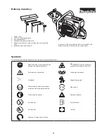
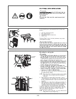
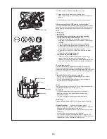
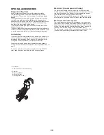
For the following work, use the assembly tools included with
delivery:
1. 13/16 AF combination wrench
2. Star-sharped wrench
3. Carburetor adjustment screwdriver
4. Adapter ring
Place the Power Cutter on a stable surface and carry out the
following assembly steps:
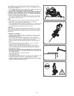
No air filter is installed!
Before operation, squeeze the supplied filter several times so
that oil is evenly immersed in the entire filter. Insert an oiled
foam filter (pre-filter), as shown in the adjacent illustration! To
do this, take off the filter cover (see the chapter on Cleaning/
changing the air filter).
Summary of Contents for EK7650H
Page 27: ...27...
Page 28: ...Makita Corporation 885023C7 www makita com ALA...


