

17
NOTE: This engine is equipped with an electronic ignition
to limit the speed. The carburetor also has a fixed jet which
cannot be adjusted.
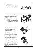
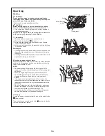
At the factory the idling speed has been set to
approx. 2,600 min
-1
, but the running-in process of a new
engine may require slight readjustment of the idling speed.
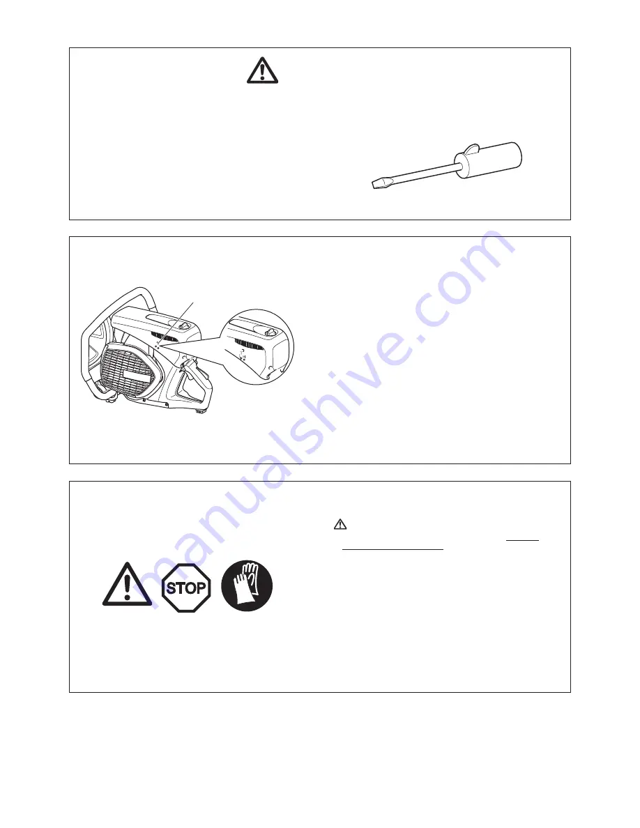
Set the idling speed with a screwdriver (width of blade: 4 mm).
A screwdriver with a molded-on lug, supplied as an optional
accessory, is useful for the adjustment.
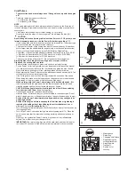
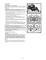
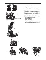
4. Idling adjustment
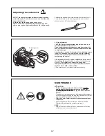
CAUTION: Carburetor adjustment may only be done by a
specialist MAKITA service center!
Do not undertake any adjustments to adjusting screws (H)
and (L) without a tachometer! Incorrect adjustment can lead
to engine damage!
A tachometer is needed for adjustments to adjusting screws
(H) and (L), because if the engine runs over its maximum
rated speed, it can overheat and run out of lubricant. This
can damage the engine!
Only adjusting screw (T) can be manipulated by the user. If
the cutting disc moves in idle
(i.e. without the throttle being
pressed)
, it is imperative to correct the idle speed!
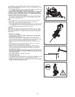
Idle speed adjustment must only be undertaken when the
engine is warm, with a clean air filter.
Use a screwdriver (4 mm blade) for idle adjustments.
Adjusting the carburetor
Adjusting screw
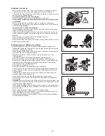
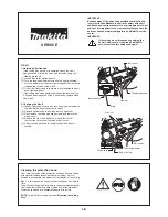
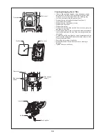
MAINTENANCE
CAUTION:
Before doing any work on the Power Cutter
•
stop the
engine and let it cool down
, remove the cutting disc,
pull the plug cap off the spark plug and wear protective
gloves!
Carrying out maintenance directly after stopping the engine or
with the plug cap on the spark plug may cause burns from hot
engine or injury from inadvertent start up.
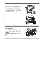
Start the Power Cutter only after complete assembly and
•
inspection.
Never use gasoline, benzine, thinner, alcohol or the like.
•
Discoloration, deformation or cracks may result.
NOTE:
Wipe off dirt from the Power Cutter and then select a clean
•
workplace to carry out maintenance.
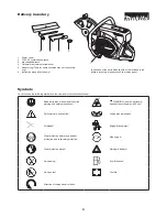
Summary of Contents for EK7650H
Page 27: ...27...
Page 28: ...Makita Corporation 885023C7 www makita com ALA...


