
P 1
0
/
19
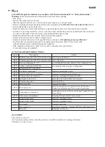
[4] DISASSEMBLY/ASSEMBLY
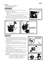
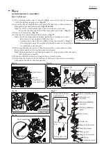
[4]-5. Carburetor
R
epair
Fig. 32
Fig. 33
Fig. 34
Fig. 35
Fig. 37
Fig. 36
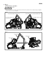
5.5x20 Hexalobular tapping
screw
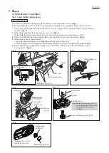
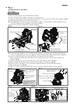
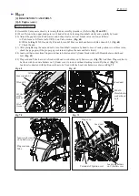
(1) After completion of the steps (1) and (2) on
[4]-4
, remove Grip cover by loosening
5.5x20 Hexalobular tapping screw. (
Fig. 32
)
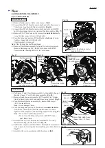
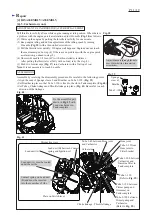
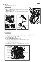
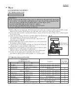
(2) Loosen two M5x45 Hexalobular socket head bolts, then remove Carburetor and
Filter gasket from Carburetor mount. (
Figs. 33 and 34
)
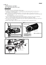
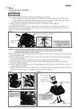
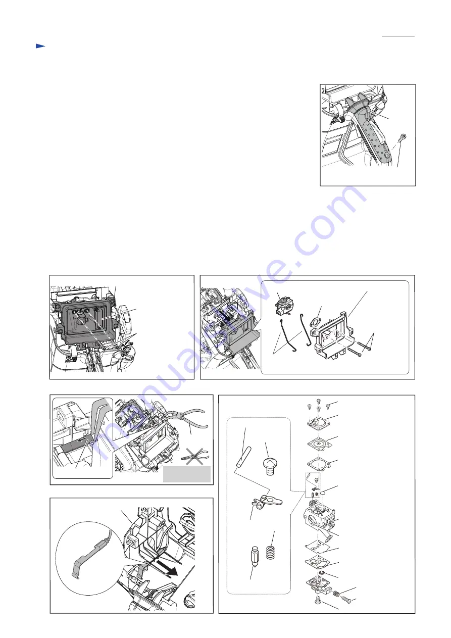
Note
: Use 1R311 to hold/ pinch Tubes to lever it up for easy removing.
Do not use the sharp edged Pliers that causes damage to Tubes. (
Fig. 35
)
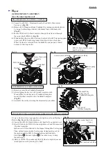
(3) Remove Contact spring. (
Fig. 36
)
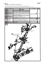
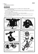
(4) Carburetor WT can be disassembled as shown in
Fig. 37
.
Note
: • Check the components’ shrinkage, hardening or breakage due to aged
deterioration. If any, replace it with a new one.
• Carburetor for some countries is different from Carburetor WT. (
Fig. 37
)
The components cannot be supplied individually because of the regulation
for compliance with standards.
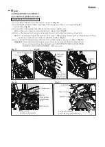
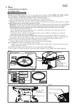
(5) Before mounting the inner parts of Pump body assembly in place, make sure that
the tip of Inlet needle valve is neither worn nor deformed.
Note
: The inner parts are not available individually. If you need some of the inner parts,
order Pump body assembly.
(6) Make sure that Inlet screen is not clogged, then set it back in place.
(7) Spray carburetor cleaner in all the fuel lines of Carburetor, then after several minutes,
wash out dirt and debris with clean gasoline.
Screw assembly (4 pcs.)
Inner parts of Pump
body assembly
M5x45
Hexalobular
socket head bolt
Filter bracket
Contact spring
Tank complete
1R311
Tube
The shape edges
damage Tubes.
Metering diaphragm
assembly
Metering cover
assembly
Metering diaphragm
gasket
Metering lever pin
Metering
lever
Inlet needle valve
Inlet screen
Carburetor WT
Throttle linkage
(2 pcs.)
Filter bracket
Grip cover
M5x45 Hexalo-
bular socket head
bolt (2 pcs.)
Carburetor gasket
Pump diaphragm
Pump gasket
Spring
Spring
Limiter cap
Pump body assembly
Screw
Screw
Pump body assembly
Idle adjust screw


