
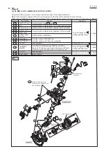
[4] DISASSEMBLY/ASSEMBLY
[4]-5. Carburetor (cont.)
R
epair
P 1
1
/
19
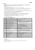
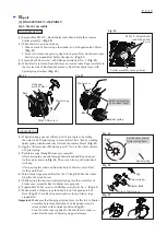
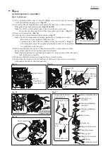
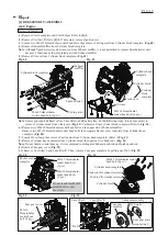
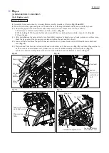
ADJUSTMENT OF CARBURETOR AFTER REPLACEMENT
ASSEMBLING
Fig. 38
Fig. 39
Fig. 40
Pull throttle lever fully after a while engine running at idle position. When there is
a problem with the engine quick acceleration, adjust H needle (
Fig. 38
) as follows:
(1) Warm up the engine by pulling the throttle lever fully for one minute.
(2) Keep engine idling and do fine adjustment of the idling speed by turning
H needle (
Fig. 38
) with a thin slotted screwdriver.
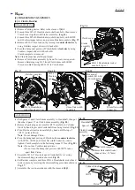
(3) Pull the throttle lever quickly. If Engine stall happens/ Engine does not reach
the maximum rpm, do step (4). If there are no problems with the engine quick
acceleration, go ahead to step (5).
(4) Unscrew H needle 1/8 turn (45°) with a thin slotted screwdriver.
After pulling the throttle lever fully with no load, retry the step (3).
(5) Push two Limiter caps (
Fig. 37
) into Carburetor with a flat top of rod.
Note
: It is not necessary to touch L needle.
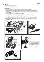
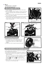
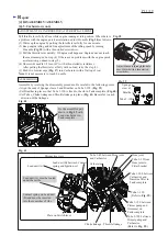
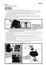
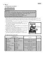
Assemble by reversing the disassembly procedure. Be careful to the following points.
• Align the ends of Sponge sleeve 9 and Breather on Tube 3-190. (
Fig. 39
)
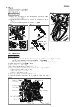
• Set Breather in place so that Tube 3-190 is fixed to the rib in Tank complete. (
Fig. 40
)
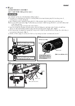
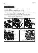
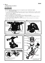
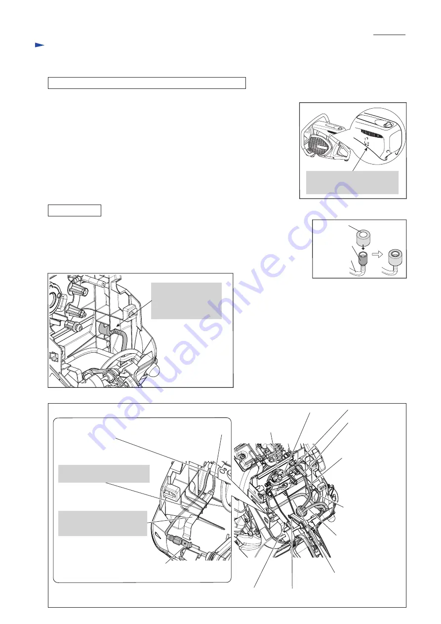
• Set Tubes, Choke linkage and Throttle linkage in place. (
Fig. 41
) Be careful to each
direction of the linkages.
Sponge
sleeve 9
Tube 3-190
Perspective view
Breather
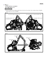
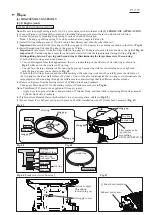
Fig. 41
Lead unit (B) between Contact
spring and Ignition oil
Carburetor
Tube 3-120 between
Primer pump and
Grommet on
Tank complete
Tube 3-300 between
Carburetor and
Gasoline filter in
Tank complete
Tube 3-190
(Refer to
Fig. 39
.)
Throttle linkage
Choke linkage
Tube 3-45 between Hose joint
and Carburetor
Tube 3-35 from
Hose joint to
Filter bracket
Hose joint
Fix the assembled part
drawn in
Fig. 39
with
Lead wire holder in
Tank complete
Lead unit (A)
Plate on Switch lever
Tube 3-190 between
Primer pump and
Carburetor
(Refer to
Fig. 39
.)
Adjust H needle through the hole
near H mark with a thin slotted
screwdriver.
Lead unit (A) must be routed
under these ribs.
Contact spring on Lead unit
(B) end must be inserted
into these notches of ribs.


