
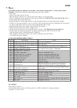
[4] DISASSEMBLY/ASSEMBLY
[4]-8. Engine
R
epair
P 1
4
/
19
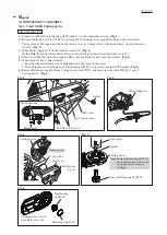
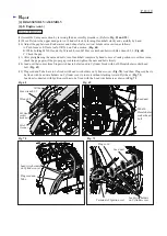
DISASSEMBLING
Fig. 48
Fig. 49
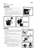
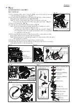
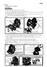
(1) Remove Clutch complete and Clutch drum. Refer to
[4]-3
.
(2) Remove Flywheel. Refer to
[4]-4
. If necessary, remove Ignition coil.
(3) Loosen five M6x25 Hexalobular socket head bolts, then remove Cutting arm from Cylinder block complete. (
Fig. 48
)
(4) Remove Exhaust muffler from Cylinder block complete.
Note
: Although Spark arrester can be removed from Exhaust muffler, it is not permitted to replace Spark arrester only
because it functions as the integrated part with Exhaust muffler.
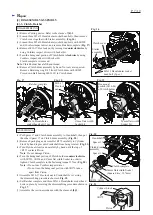
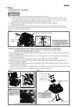
(5) Remove Oil case from Cylinder block complete. (
Fig. 49
)
Note
: Unless you repair Exhaust valves, Cam lifters, and Rocker arms, do the following steps. It is not necessary to
remove Cylinder block from Crank case (
Fig. 49
)/ Carburetor from Cylinder block complete (Refer to
Fig. 34
.)
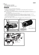
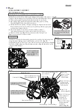
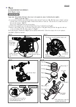
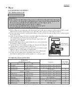
(6) Remove two M6x20 Hexalobular socket head bolts on the upper side of Exhaust muffler.
Remove two M5x25 Hexalobular socket head bolts then separate Rocker cover complete from Cylinder head
complete. (
Fig. 50
)
(7) Loosen Hose clamp then remove Suction line from Cylinder head complete. (Refer to
Fig. 41
)
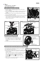
(8) Remove Cylinder head complete from Cylinder block, then pull out two Push rods. (
Fig. 51
)
Note
: Do not failure to mix them up. It is recommend to distinguish Exhaust push-rod and Intake push-rod.
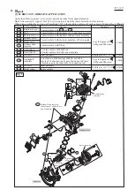
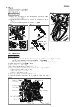
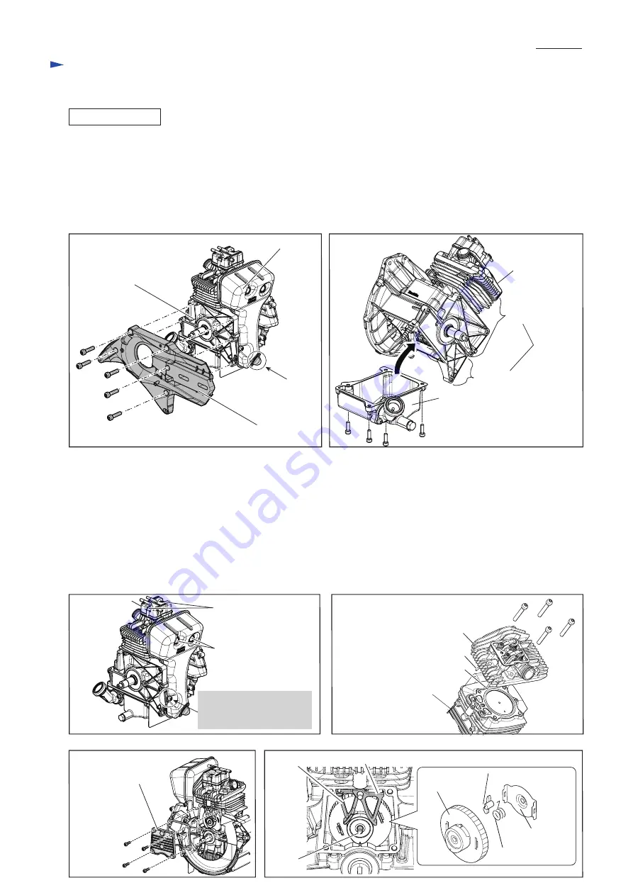
(9) Remove Cam gear cover (
Fig. 52
).
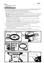
(10) Remove Cam lifter L and Cam lifter R. Then, remove Cam gear complete by pulling out Pin 5. (
Fig. 53
)
M5x16 Hexalobular
socket head bolt (4 pcs.)
M5x16
Hexalobular
socket head
bolt (4 pcs.)
Cam gear cover
M6x25 Hexalobular
socket head bolt (5 pcs.)
Oil case
Cylinder block
Crank case
Cylinder
block
complete
Cylinder head
complete
Cylinder block complete
Cutting arm
Exhaust
muffler
Spark arrester
Fig. 50
Fig. 51
Fig. 52
Fig. 53
M6x20 Hexalobular
socket head bolt
(2 pcs.)
Cylinder block
Cam lifter L
Pin 5
Cylinder head complete
M5x25 Hexalobular
socket head bolt
(2 pcs.)
M6x35 Hexalobular socket
head bolt (4 pcs.)
Rocker cover
complete
Push rod (for exhaust system)
Push rod (for intake system)
Cam lifter R
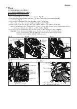
Cam gear assembly
Cam gear
complete
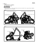
Fly weight
Cam gear plate
Torsion spring 9
Do not touch this M6x20
Hexalobular socket
head bolt.


