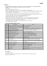
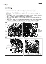
[4] DISASSEMBLY/ASSEMBLY
[4]-8. Engine (cont.)
R
epair
P 1
6
/
19
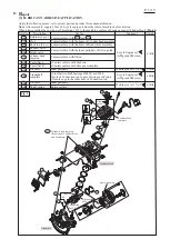
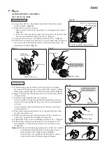
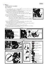
DISASSEMBLING
Fig. 58
M6x30 Hexalobular
socket head bolt (8 pcs.)
Cylinder block
Slotted
screwdriver
Cylinder block
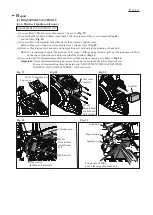
Top ring
Second ring
Oil ring
Piston
Piston pin
Ring spring 12
Crankshaft
complete*
Flat washer 41
Oil seal L
*The components cannot be
supplied individually.
Ring spring 12
Woodruff key 4
Oil seal 17
M5x16
Hexalobular
socket head
bolt (3 pcs.)
Crank case viewed
from the bottom
side
Crank case viewed from the bottom side
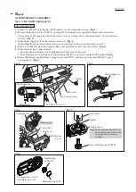
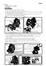
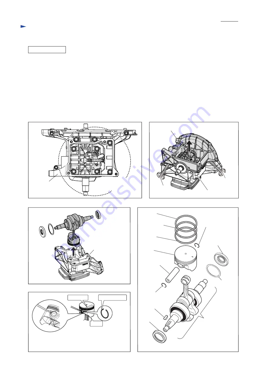
Important: When Intake/ Exhaust valves have to be replaced, remove Cylinder head complete.
(Refer to previous page.)
(5) Loosen eleven Hexalobular socket head bolts on the bottom of Crank case (
Fig. 58
), then remove Crank case from
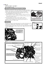
Cylinder block. As Liquid gasket makes Cylinder block stick on Crank case, insert and twist a slotted screwdriver
between the clearance. (
Fig. 59
)
Scrape away Liquid gasket on the mating surface.
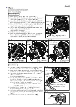
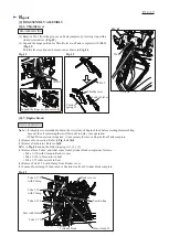
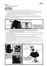
(6) Pull out the assembled part of Crank shaft and Piston from Cylinder block. (
Fig. 60
)
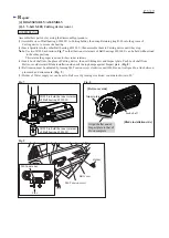
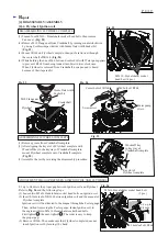
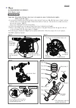
(7) Remove one of Ring spring 12 with a thin slotted screwdriver, then push Piston pin from the opposite with care
so as not to damage the other Ring spring 12. (
Fig. 61
)
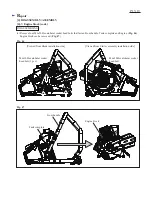
The following parts mentioned in
Fig. 62
can be replaced individually. When the rest parts have to be replaced,
Crankshaft complete is required.
Fig. 59
Fig. 61
Fig. 62
Fig. 60
Insert a thin slotted screwdriver
from the depression on the rib
around Piston pin hole.
Piston pin
Ring spring 12
Piston
Slotted
screwdriver


