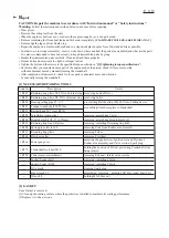
background image

Hood section

V belt 5-800

Cutting device

[4] DISASSEMBLY/ASSEMBLY

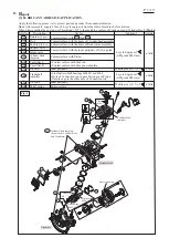
[4]-1. V-belt 5-800, Cutting device

R

epair

P  

4

19

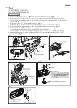
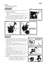
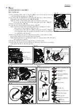
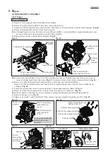
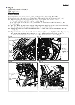
(1) Loosen two M8 Hex nuts slightly with Wrench 13-16 of a standard accessory. (

Fig. 2

)

(2) Release the tension on V-belt 5-800 by turning M6 Tensioning screw counterclockwise with Screwdriver.

      The position of M6 square nut shows the tension level; as it comes close to the minus mark, the belt tension is 

      relieved. (

Fig. 2

)

(3) When Water supply set is on the machine, remove it. (

Fig. 3

)

      Holder (

Fig. 2

) can be removed from Belt cover by turning clockwise/ counterclockwise to 90° .     

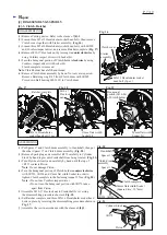
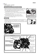
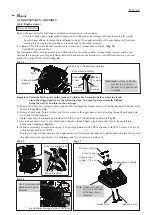
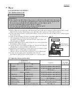
(4) Remove two M8 Hex nuts, then separate Belt cover and Hood section from the machine. (

Fig. 4

)

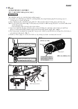
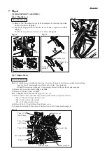
(5) When Hood section is disassembled:

      1. Face the blade installation side of Spindle toward the ram of Arbor press.

      2. Press Spindle out of Cutting device. Ball bearing 6203LLU is removed together with Spindle. (

Fig. 5

)

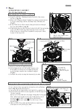
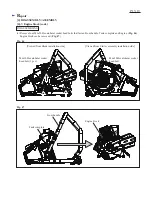
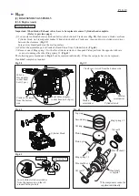
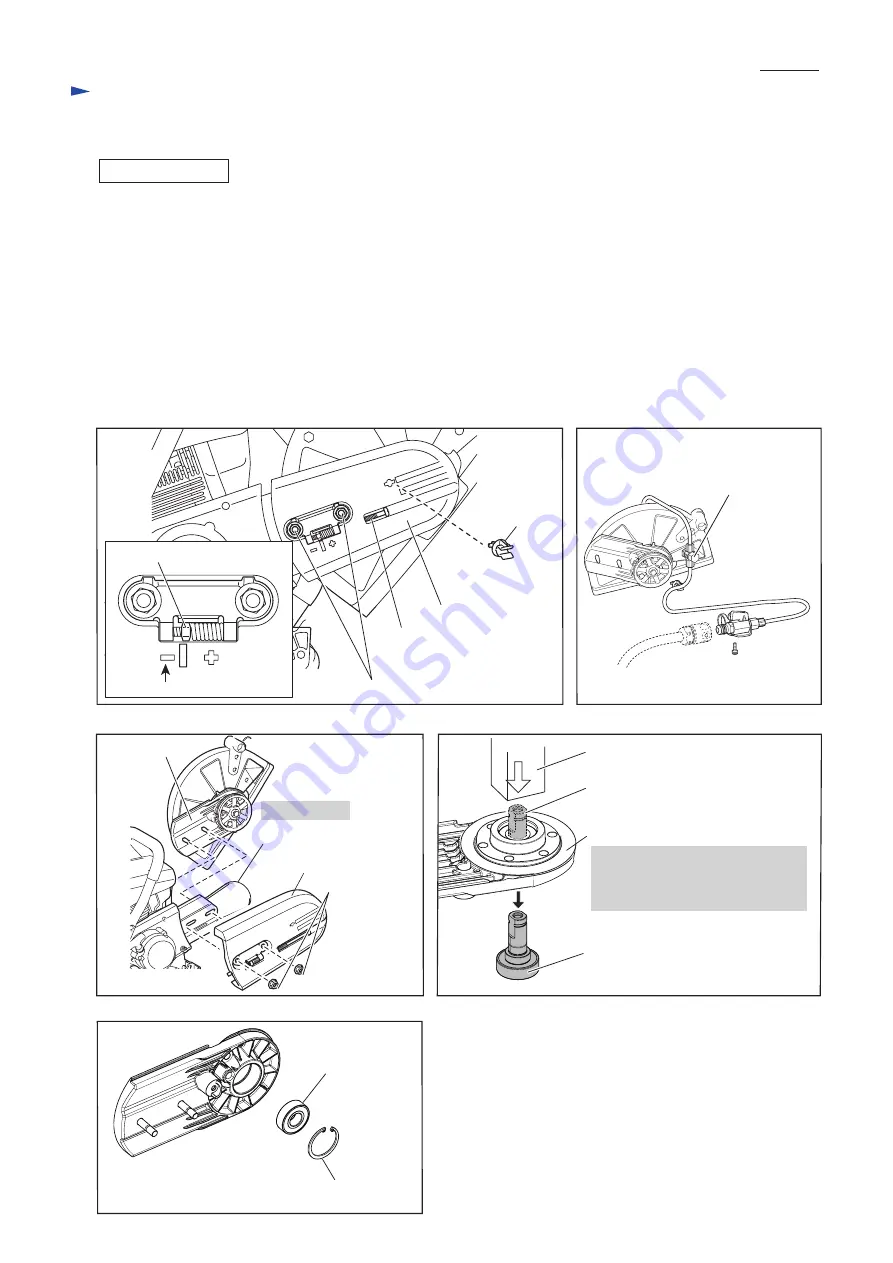
(6) Remove Retaining ring R-40 from Cutting device with 1R291, and then press the other 6203LLU out of 

      Cutting device. (

Fig. 6

)

Fig. 2

Fig. 3

Fig. 5

Fig. 6

Fig. 4

M8 Hex nut (2 pcs.)

Minus mark

M8 Hex nut

(2 pcs.)

M6 Square nut

Cutting device 

Note

: Another Ball bearing 6203LLU

           and Retaining ring R-40 are left

           in Cutting device as drawn 

           in

 Fig. 6

.

Cutting device viewed

from Belt cover side

Arbor press

Spindle

One of Ball bearing 6203LLU 

Ball bearing

6203LLU 

Retaining ring R-40

M6 Tension screw

Belt cover

Belt cover

Water supply set

DISASSEMBLING

Holder

Summary of Contents for EK7650H

Page 1: ...nk capacity L US oz Fuel consumption L h US oz h Wheel diameter mm Engine Displacement cm cu in Max output kW 4 6 at 5 500 min Max torque N m 4 stroke Specifications EK7651H Model Type Decompression v...

Page 2: ...after you mounted a main part of the engine such as the piston check if it moves smoothly without abnormal noise by manually turning the crankshaft After completion of reassembly check for loose part...

Page 3: ...h the holes of Cylinder head assembly Repair Inner periphery a little Makita grease N No 2 Inner periphery Oil seal 17 Cam lifter R Crankshaft complete Oil seal L P 3 19 109 112 117 Cylinder head comp...

Page 4: ...ate Belt cover and Hood section from the machine Fig 4 5 When Hood section is disassembled 1 Face the blade installation side of Spindle toward the ram of Arbor press 2 Press Spindle out of Cutting de...

Page 5: ...ers 3 Insert Lock shaft into the place of Cutting device then set Sliding disc and Impact plate Push Lock shaft from Belt cover side toward Blade installation side until the top bumps against Impact p...

Page 6: ...e one end through Starter knob and Rope stopper tie the end as drawn in Fig 14 Then cover the top of Starter knob with Cap After passing the other end from the hole of Starter case to Reel tie the end...

Page 7: ...om being rotated Fig 21 3 Turn Flywheel slowly and carefully by hand until the top of 1R372 contacts Piston Note Do not damage Piston 4 Turn the hexagonal portion of Clutch holder counterclockwise wit...

Page 8: ...G FLYWHEEL COMPLETE ASSEMBLING FLYWHEEL COMPLETE Fig 23 Fig 24 Fig 25 M10 Flange nut Flywheel Crankshaft 14mm flats width Socket bit Screwdriver Water pump pliers Woodruff key in key way of Crankshaft...

Page 9: ...to apply the principle of leverage Without being forced to pull put the long noses of Pliers on the edge of Ignition coil and lever up the flag terminal Fig 31 5 Loosen two M5x16 Hexalobular socket he...

Page 10: ...on for compliance with standards 5 Before mounting the inner parts of Pump body assembly in place make sure that the tip of Inlet needle valve is neither worn nor deformed Note The inner parts are not...

Page 11: ...Assemble by reversing the disassembly procedure Be careful to the following points Align the ends of Sponge sleeve 9 and Breather on Tube 3 190 Fig 39 Set Breather in place so that Tube 3 190 is fixe...

Page 12: ...ed it is necessary to remove Engine from Tank complete 1 Remove Hood section Refer to Fig 4 of 4 1 2 Remove Carburetor Refer to 4 5 Refer to Fig 45 and do the following steps 3 4 5 3 Remove three Tube...

Page 13: ...bular socket head bolts that fasten Front handle Tank complete and Engine Fig 46 Engine block can be removed Fig 47 Viewed from Blade installation side Viewed from Starter assembly installation side E...

Page 14: ...complete from Cylinder head complete Fig 50 7 Loosen Hose clamp then remove Suction line from Cylinder head complete Refer to Fig 41 8 Remove Cylinder head complete from Cylinder block then pull out t...

Page 15: ...ith 1R308 and remove Rocker arms Refer to Figs 50 and 54 2 Remove Spark plug Turn Flywheel until Piston comes to the upper dead point by looking through Spark plug hole on Cylinder head complete Note...

Page 16: ...cket head bolts on the bottom of Crank case Fig 58 then remove Crank case from Cylinder block As Liquid gasket makes Cylinder block stick on Crank case insert and twist a slotted screwdriver between t...

Page 17: ...ng by placing Second ring with the red marking on your right and with the ring gap near you as shown in Fig 65 If both of the two rings are used and the white marking of Second ring is rubbed off care...

Page 18: ...rank portion two or three turns check the gap again if the proper gap is obtained tighten the nuts and bolts firmly 12 Lead unit that comes from Stop switch has to be fastened to Cylinder block with 6...

Page 19: ...ted place 7 If spark is not produced replace Spark plug with a new one then check for spark by following the procedure 1 to 6 once again WARNING When a spark is produced high voltage current is delive...

Reviews: