
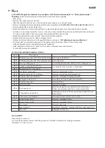
[4] DISASSEMBLY/ASSEMBLY
[4]-2. Starter assembly
R
epair
P
6
/
19
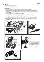
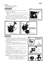
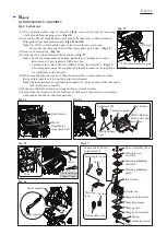
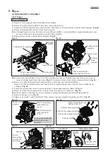
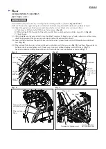
(1) Loosen three M5x19 - Hexalobular socket head bolts, then remove
Starter assembly. (
Fig. 10
)
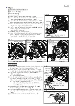
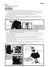
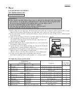
(2) When Starter rope is not broken;
1. Make a slack of Starter rope then hook it on U-shaped notch of Reel.
(
Fig. 11
)
2. Be sure to loosen the spiral spring force by turn Reel clockwise to spin
Starter rope around Reel before the step (3). (
Fig. 11
)
(3) Loosen M6x20 Set screw with Phillips screwdriver No. 3. (
Fig. 11
)
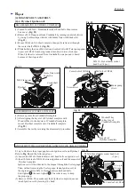
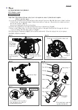
(4) When Reel is removed from Starter case, insert a index finger carefully to
the reverse side of Reel and then remove Reel from Starter case with
Spiral spring attached. (
Fig. 12
.)
Fig. 10
Fig. 13
Fig. 11
DISASSEMBLING
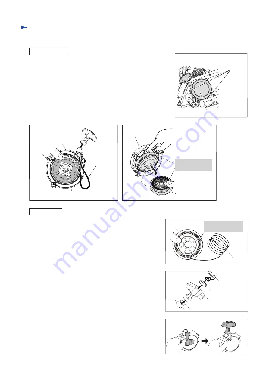
ASSEMBLING
Fig. 12
(1)
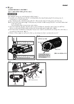
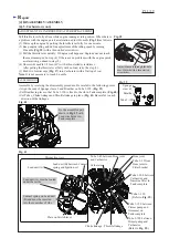
If Spiral spring pops out of Reel, put it back in place by setting
the outer end of Spiral spring in place in Reel first, then by winding
Spiral spring counterclockwise towards the center of Reel. (
Fig. 13
)
(2) Apply a little amount of Makita grease N No.2 to the whole surface
of Spiral spring.
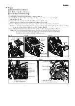
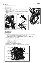
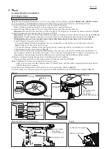
(3) Put Starter rope through Starter case complete.
After passing the one end through Starter knob and Rope stopper,
tie the end as drawn in
Fig. 14
. Then cover the top of Starter knob
with Cap.
After passing the other end from the hole of Starter case to Reel,
tie the end in Reel.
(4) Wind Starter rope around Reel for the 2/3 length (When the whole
length is 1m, wind 66cm.)
(5) While setting the inner end of Spiral spring into the center slot of
Starter case, assemble Reel to Starter case properly.
(6) Tighten M6x20 Set screw with Phillips screwdriver No. 3. (
Fig. 11
)
(7) Make a slack of Starter rope then hook it on U-shaped notch of
Reel. (
Fig. 11
) Turn Reel counterclockwise to spin Starter rope
around Reel.
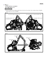
Important
: Make sure that the proper spring force is effective to Starter
assembly by turning Starter knob by hand and it can be
returned back to the original position. (
Fig. 15
)
Even if Starter rope is pulled to the full, there is room to
rotate Reel because of Spiral spring performance.
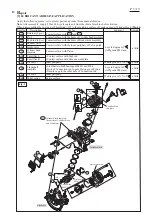
M5x19 - Hexalobular
socket head bolt
(3 pcs.)
Reel
Starter case
Starter assembly (gray portion)
Starter rope
Reel
U-shaped
notch of Reel
M6x20 Set screw
Spiral spring
Spiral spring
Reel
Fig. 14
Fig. 15
Rope stopper
Cap
Starter knob
Hole of Starter case
Hold Spiral spring
by an index finger.
Set the outer end of
Spiral spring here.


