P
5
/ 1
8
R
epair
[4] DISASSEMBLY/ASSEMBLY
[4]-4. Pipe complete
DISASSEMBLING
ASSEMBLING
Assemble by reversing the disassembly procedure.
Note
: Set Loop handle set and Control lever in place so that the hole of Pipe complete faces upward. (
Fig. 11
)
Pipe complete
Loop handle set
(* mark: The components)
Shaft
M5x16 Hex socket head bolt with
flat washer and spring washer
Trimmer head ass’y
Rag
* M5x25 Hex
socket head bolt
(2 pcs.)
* Clamp cover B
Control lever ass’y
M5x14 Hex socket
head bolt (2 pcs.)
4x18 Hex socket
head Tapping
screw (4 pcs.)
M5x25 Hex socket head bolt
Fig. 8
Fig. 11
Fig. 9
Fig. 10
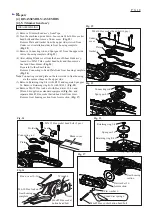
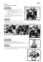
(1) Remove M5x16 Hex socket head bolt
with flat washer and spring washer
and M5x25 Hex socket head bolt, and then
separate Trimmer head ass’y from Shaft and Pipe complete manually or using Waterpump pliers and Plastic hammer
as drawn in
Fig. 8
.
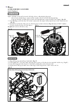
(2) Remove Loop handle set by separating two M5x25 Hex socket head bolts from Clamp cover B.(
Fig. 9
)
(3) Remove two M5x14 Hex socket head bolts and four 4x18 Hex socket head bolts, and then separate Control lever ass’y
from Pipe complete. (
Fig. 10
)
(4) Remove Pipe complete. Refer to
[4]-3 Separation of Pipe from Trimmer head ass’y
.
(5) Pull out Shaft from Pipe complete.
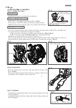
The hole of
Pipe complete
500 ± 2mm
82 to 87mm
When Pipe complete is assembled to Engine,
M5x12 Hex socket head bolt (refer to Fig. 4
of the previous page) must reach the hole as
the stopper for Engine on Pipe complete.


