P
6
/ 1
8
R
epair
[4] DISASSEMBLY/ASSEMBLY
[4]-5. Trimmer head ass’y
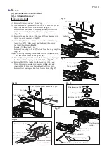
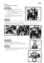
(1) Remove Trimmer head ass’y from Pipe.
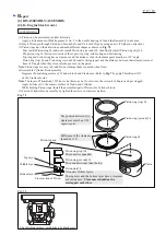
(2) Turn the machine upside down. Loosen six M4x16 Hex socket
head bolts and then remove Under cover. (
Fig. 12
)
Remove Plate and Gasket from the upper side (viewed from
Under cover installation side) in Gear housing complete.
(
Fig. 12
)
(3) Remove Connecting rod and Spur gear 43 from the upper side
in Gear housing complete. (
Fig. 13
)
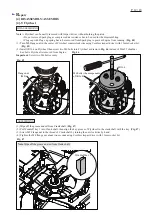
(4) After sliding Blade cover from the base of Shear blade ass’y,
loosen two M5x25 Hex socket head bolts and then remove
Seal and Shear blades. (
Fig. 14
)
Be careful to the shear blades.
Remove Connecting rod and Plate from Gear housing complete.
(
Fig. 14
)
Note
: Connecting rod and plate on the lower side in Gear housing
are the same as those on the upper side.
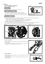
(5) Remove Retaining ring S-8 with 1R291 and separate Spur gear
24. Remove Retaining ring R-26 with 1R291. (
Fig. 15
)
(6) Remove M6-10 Hex lock nut with Box driver 10-16 and
Wrench 4 supplied as standard equipment (
Fig. 16
), and
separate M6x85 Hex socket button head bolt from Joint.
Remove Gear housing section from Joint section. (
Fig. 17
)
M4x16 Hex socket head bolt (6 pcs.)
M5x25 Hex socket head bolt (2 pcs.)
Under
cover
Fig. 12
Fig. 14
Fig. 13
Fig. 15
Plate
Blade cover
Gasket
Connecting rod
Seal
Holder
Plate
Connecting rod
Retaining ring S-8
Retaining ring R-26
Spur gear 24
Spur gear 43
Fig. 16
Fig. 17
Wrench 4
Joint
M6-10 Hex lock nut
Box driver 10-16
Gear housing
complete
Gear housing
section
Coned disc spring 6
Joint section
Flat washer 6
M6x85 Hex socket
button head bolt
Flat washer 36
M6x85 Hex socket button head bolt
DISASSEMBLING


