
P
7
/
7
W
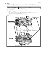
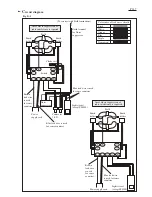
iring diagram
Fig. D-2
Light circuit
(Except FS4000)
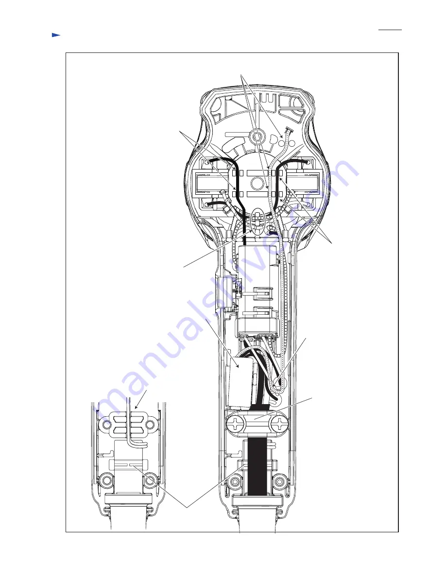
Strain relief*
Insert Lead wires of Light circuit into grooves of
Motor housing before clamping Power supply cord
with Strain relief* and two 4x18 Tapping screws.
(Except FS4300TP)
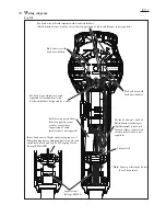
Put the Lead wire’s slack of
Earth terminal in this space.
(Earth terminal is not used
for areas where suppression
of radio interference is not
required.)
Fix Lead wire of Earth terminal with Lead wire holders.
(Earth terminal is not used for areas where suppression of radio interference is not required.)
Fix Lead wires which are passed
right and left around here, with
Lead wire holders designated by a circle.
Put Noise suppressor here.
(Noise suppressor is not
used for areas where
suppression of radio
interference is not required.)
Brush holder
Brush holder
Fix Lead wire with
Lead wire holders.
Fix Lead wire with
Lead wire holders.
* Note: Some specifications do not
have Strain relief.


